Communications
6G FWA: Broadband Beyond Smartphones
Introduction
Fixed Wireless Access (FWA) is emerging as an important broadband vertical for 6G. Unlike traditional fixed broadband, which depends on fiber deployment, FWA can provide high-speed connectivity without last-mile wired infrastructure. This makes it especially attractive in areas where fiber rollout is difficult or costly due to geography, terrain, or deployment regulations.
The growth of 5G FWA accelerated with the availability of mid-band spectrum, even though FR2 offers much larger bandwidth. This highlights a key reality for 6G: FR1 remains essential for practical deployment, while FR2 still faces challenges in sustaining robust and reliable broadband service. At the same time, operators are seeing a structural imbalance—FWA traffic is growing rapidly and is typically much heavier than conventional mobile traffic, while the corresponding revenue increase is relatively limited. Unless handled efficiently, FWA may increasingly compete with regular mobile services for scarce radio resources.
These trends point to two key priorities for 6G FWA. The first is to improve FR1 spectrum efficiency, especially through uplink enhancement, by reducing unnecessary overhead in measurement, feedback, and control procedures. The second is the sustainment of FR2, so that its large bandwidth can be translated into stable and practical broadband delivery.
Fortunately, FWA has several characteristics that can be directly exploited. CPEs have a larger form factor than handheld devices, enabling more antennas, higher transmit capability, and operation without tight battery constraints. In addition, FWA channels are often quasi-static because CPEs are fixed. These properties open new opportunities to redesign uplink operation and improve sustained FR2 performance. In this article, we focus on these two directions for 6G FWA evolution: FR1 uplink enhancement for better spectrum efficiency and sustainment of FR2 for robust high-capacity broadband delivery.
What aspects of FWA device can be differ from smartphone
Key differences between FWA devices and smartphones
• Larger form factor: more antennas, wider spacing, higher-gain implementation
• Fewer power constraints: no tight battery limitation, enabling stronger and more sustained transmission
• Fixed installation: stable placement and less random movement
• Quasi-static channels: lower signaling and measurement overhead can be targeted
• Different service goal: sustained premises broadband rather than mobile user-centric connectivity
These differences make it clear that FWA should not be treated simply as another smartphone-like usage scenario on top of the existing mobile air interface. Its larger device form factor, relaxed power constraints, fixed installation, and quasi-static channels together create room for a different design philosophy—one that prioritizes sustained broadband delivery over mobility-centric operation. In other words, FWA is not merely a new traffic profile; it is a service scenario with distinct device assumptions and radio conditions.
This observation directly motivates the two technical directions discussed in the rest of this article. First, the quasi-static nature of FWA links opens opportunities to redesign uplink procedures in FR1 with lower overhead and better spectrum efficiency. Second, the stronger hardware capability and installation stability of FWA devices make it possible to pursue more robust and sustainable operation in FR2. Together, these directions point to a more FWA-aware 6G air interface.
FR1 Uplink Enhancement for Better Spectrum Efficiency
Although FWA traffic is often viewed as downlink-dominant, uplink design still plays an important role in overall spectrum efficiency. Modern FWA services increasingly rely on stronger uplink capability for applications such as video collaboration, cloud backup, and distributed AI processing. More importantly, many of today’s uplink mechanisms in 5G NR were originally designed around the constraints of handheld smartphones. This creates a clear mismatch for FWA CPEs, which have larger form factors, more flexible antenna implementations, and fewer power constraints.
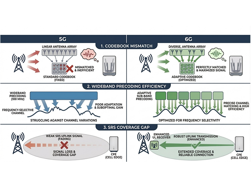
Figure 1. 5G Limitation and 6G Potential of FWA in FR1
From an FWA perspective, three limitations of the current 5G NR uplink are particularly important. First, the existing UL codebook is based on DFT assumptions that fit only limited antenna geometries, while practical FWA CPE designs can be much more diverse. Second, 5G NR effectively relies on wideband uplink precoding, which can be inefficient when a large uplink bandwidth experiences strong frequency selectivity. Third, uplink scheduling and link adaptation typically depend on Sounding Reference Signals (SRS), but SRS coverage is limited by device transmit power, which can become a bottleneck especially for cell-edge CPEs.
These limitations point to three promising directions for 6G FWA in FR1: more flexible UL codebooks, subband-based precoding, and SRS-free uplink operation.
• Flexible UL Codebooks for Diverse CPE Antenna Structures
One major limitation of today’s 5G uplink is that its codebook design does not fully reflect the diversity of practical FWA CPE antenna structures. Unlike smartphones, FWA devices can adopt a wider range of antenna layouts, and this makes a single rigid codebook less effective.
A first step forward is a new fixed UL codebook designed to provide robust performance across a broader set of antenna configurations. Rather than assuming a narrow array model, such a codebook can be optimized for more general worst-case conditions. For example, simulation results show that a Grassmannian-based codebook can outperform the legacy 5G UL codebook in representative four-port cases, making it a strong candidate for a 6G baseline design.
Beyond this baseline approach, an even more powerful option is a downloadable UL codebook. In this framework, the base station assigns a small set of precoders tailored to a specific CPE, and later indicates which precoder should be used for PUSCH transmission. Because FWA channels are quasi-static, this customized codebook can be derived from observed uplink channel behavior over time. The result is not only higher throughput, but also lower long-term signaling overhead and better adaptability to future CPE antenna designs.
• Subband Precoding over Wide Uplink Bandwidth
FWA CPEs are expected to support wider uplink bandwidths than conventional handheld devices. In this setting, forcing a single wideband precoder across the full bandwidth can significantly reduce transmission efficiency when the channel is frequency selective.
Subband precoding offers a more suitable solution by allowing the transmit precoder to better match variations across frequency. This is particularly valuable for wideband FWA uplink, where different parts of the channel may experience meaningfully different propagation conditions. System-level evaluation shows clear gains from this approach, with throughput improvements of up to around 20% compared with wideband precoding.
• SRS-Free Uplink Transmission
Another important opportunity comes from the deployment characteristics of FR1 FWA itself. Since FWA in FR1 is typically deployed in TDD spectrum, downlink-uplink reciprocity can be exploited. Instead of relying only on uplink SRS for scheduling and link adaptation, the CPE can estimate the uplink channel from downlink reference signals such as CSI-RS and report the result to the base station.
This enables SRS-free uplink transmission, reducing dependence on uplink sounding coverage. The benefit is especially significant for cell-edge CPEs, where SRS reception may be weak or unreliable. Simulation results indicate that this approach can deliver very large gains in user-perceived throughput, substantially outperforming conventional SRS-based uplink transmission.
Taken together, these techniques show that FR1 uplink design for 6G FWA should move beyond smartphone-oriented assumptions. By redesigning codebooks, enabling subband precoding, and reducing dependence on SRS, 6G can make FR1 operation much more spectrum-efficient for fixed broadband delivery.
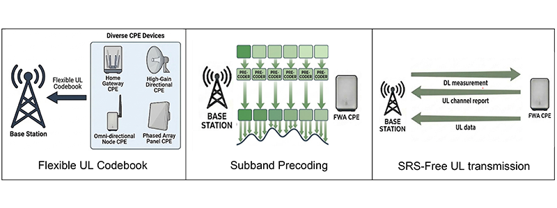
Figure 2. Techniques for FR1 Uplink Enhancement
Sustainment of FR2 for Practical Broadband Delivery
FR2 remains one of the most attractive spectrum options for 6G FWA because it offers the wide bandwidth needed for truly high-capacity broadband delivery. But wide bandwidth alone does not make FR2 practical. For FWA, the real challenge is not just reaching a high peak data rate, but sustaining that performance under everyday deployment conditions.
This is where today’s 5G NR design reveals a clear limitation. Because FR2 signals suffer from high path loss, the system depends on highly directional beamforming with narrow beams. In 5G NR, finding and maintaining these beams typically relies on beam sweeping, where the base station and device test multiple candidate directions before selecting one. While this works in principle, it comes at a cost: high overhead, high latency, and limited beam accuracy. A significant amount of radio resource is spent simply on finding the right beam, and whenever the beam must be re-aligned, the same burden appears again.
Even in FWA, where the CPE is fixed, this problem does not disappear. The device may stay in one place, but the environment does not. Trees move, vehicles pass, and local blockage can still disturb a narrow FR2 beam. In addition, if many FWA users must be served from the same site, conventional single-beam operation does not fully exploit the spatial capability of FR2 arrays. This suggests that 6G should not simply inherit the 5G FR2 framework as it is.
Instead, three directions appear especially promising for making FR2 more practical for FWA: faster beam acquisition, more proactive beam continuity, and more efficient support for multiple fixed users.
• From Beam Sweeping to Differential Beamforming
A first opportunity is to simplify how the best beam is found. In 5G NR, beam management is largely based on searching across a predefined set of beams. This creates unavoidable signaling overhead, especially when narrow beamwidth and dense beam sets are needed.
Differential Beamforming (DBF) offers a more efficient alternative. Rather than searching beam by beam, DBF estimates the correct beam direction more directly by using a correlated beam pair, often described as a sum beam and a differential beam. By comparing the signals associated with these two beams, the system can infer how the beam should be adjusted toward the optimal direction.
This changes the beam management philosophy from searching to estimating. The benefit is clear: beam acquisition can be performed with far fewer measurement occasions, which reduces both overhead and delay. At the same time, DBF can achieve finer beam alignment than a fixed codebook search, helping the system approach the true best beam rather than just the nearest available one. For FWA, where beam directions are relatively stable over time, this kind of direct estimation becomes especially attractive.
• From Beam Failure Recovery to Beam Failure Prevention
A second opportunity is to rethink what happens when the link begins to degrade. In current 5G NR FR2 operation, this is mainly handled through Beam Failure Recovery (BFR). The problem is that BFR is reactive: the system first detects that the link has already become unreliable, and only then starts the recovery process. This adds latency, control overhead, and sometimes a user-visible service interruption.
For 6G FWA, a better approach is Beam Failure Prevention (BFP). Instead of waiting until the beam has effectively failed, the system should act earlier and switch beams before the link drops to that point. This idea is particularly well suited to FWA because the CPE continuously observes downlink beam quality and often has the best view of whether the current link is about to degrade.
A natural starting point is UE-initiated beam reporting, where the device proactively reports candidate beams when beam quality begins to fall. Building on this idea, 6G can introduce a more complete prevention-oriented framework: dedicated beam-quality events, lightweight network responses such as fast TCI state updates, and even UE-initiated beam switching under controlled conditions. The result is a more proactive beam management design that reduces latency and overhead while improving service continuity.
• Simultaneous Multi-Beam for Supporting More FWA Users
A third opportunity is to use FR2 beamforming not only for link robustness, but also for spatial scalability. In many FWA deployments, multiple homes or premises are served from the same site, and their angular locations remain stable over long periods. This creates a favorable condition for simultaneous multi-beam operation.
In current systems, beam management is often focused on maintaining one strong beam per user. But FR2 arrays can potentially generate multiple beams at the same time, allowing the base station to serve different fixed users in different directions within the same scheduling interval. For FWA, this is particularly promising because user locations do not change rapidly, making the spatial relationship between users much more predictable than in handheld mobility scenarios.
This can improve FR2 operation in two ways. First, it increases capacity, because more FWA users can be served concurrently rather than one after another. Second, it improves spatial efficiency, because highly directional beams aimed at well-separated fixed users may cause only limited mutual interference. In other words, the same directional nature that makes FR2 fragile can also become an advantage when the network learns how to exploit stable spatial separation across multiple FWA users.
To support this direction in 6G, enhancements may be needed in beam scheduling, interference-aware transmission, and CPE capability reporting. But the overall idea is simple: if FR2 is to become a scalable broadband layer for FWA, it should not only maintain one link well, but also support many links efficiently.
Taken together, these three directions show that sustaining FR2 in 6G FWA is not simply about using wider bandwidth. It requires a different beam management philosophy: one that reduces the cost of beam acquisition, avoids unnecessary recovery through prevention, and makes better use of spatial multiplexing to support more fixed users. With this shift, FR2 can move closer to becoming a practical, reliable, and scalable broadband layer for 6G FWA.
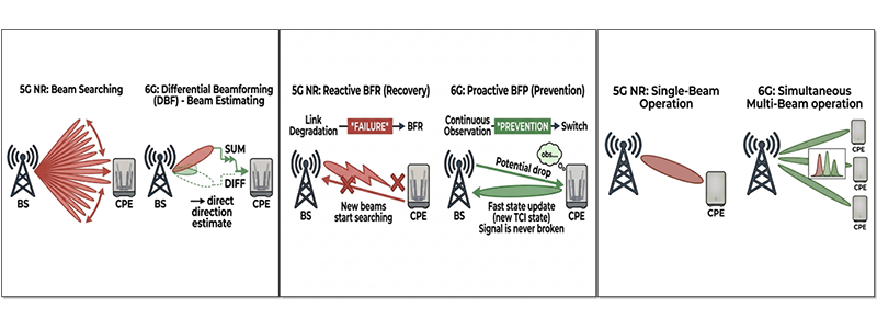
Figure 3. Techniques for FR2 Enhancement
Testbed for differential beamforming
To verify the feasibility of proposed DBF in realistic environment, hardware test is performed. The tested scenario is shown in Fig. 4. In this test scenario, a BS functioned with the proposed DBF scheme is probing a drone which is regarded as differently located CPE users. The BS estimates the angular direction based on simultaneous processing of sum beam and differential beam on the received signal from the drone. In the test, the antenna panel of BS is divided into four sub-panels and a Rx DBF is implemented based on this antenna structure. Specifically, mmW band with carrier frequency 28 GHz is used and antenna panel used in the hardware test consists of 256 antenna elements, forming a 16 × 16 UPA. The hardware test results on the angular adjustment estimation are shown in Table. I. From these results, it can be observed that with the aid of DBF, it is feasible to get accurate angular domain estimation with granularity of 0.05 degree. It then can facilitate BS to assign better beam to CPE UEs in different locations.
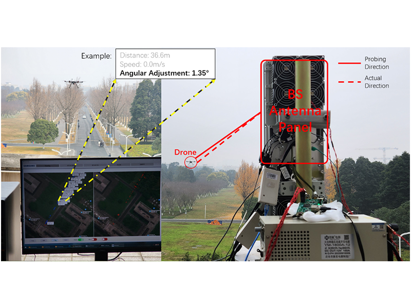
Figure 4. Validation in a hardware test-bed
Conclusion
FWA is emerging not simply as an extension of mobile broadband, but as a distinct 6G vertical with its own device assumptions and deployment characteristics. This calls for an air-interface design that moves beyond smartphone-centered thinking and better reflects the realities of fixed broadband delivery.
In this blog, we highlighted two key directions for 6G FWA evolution: improving FR1 uplink efficiency to reduce spectrum cost, and sustaining FR2 operation through faster beam management, proactive continuity, and more scalable support for fixed users. Together, these directions show that the success of 6G FWA will depend not only on wider bandwidth, but also on a more FWA-aware design philosophy across both FR1 and FR2.