Communications
Coherent Joint Transmission (CJT): High-Capacity Enabler for 6G
Introduction
Since LTE, cooperative transmission across multiple transmission-reception points (TRPs) has been shown to enhance network (NW) spectral efficiency and coverage for downlink (DL), thereby improving user experience. Despite its potential, multi-TRP deployment was absent mainly due to the need for low-impairment backhaul to enable tight coordination among the TRPs within the NW. For this reason, much effort was spent on non-coherent joint transmission (NCJT), which requires less coordination since beamforming is performed separately across TRPs. Unfortunately, NCJT offers a marginal gain in spectral efficiency and coverage.
As active antenna arrays and software-based RAN are more common, stable coordination among TRPs becomes more feasible with much less backhaul impairments. Even more so, coordination among collocated TRPs in a same site can be regarded as near-ideal. This facilitates coherent joint transmission (CJT) where coherent beamforming is performed across TRPs. With CJT, the TRPs not only provide a larger aggregate antenna array for higher beamforming gain, but also transmit a same set of data streams (termed layers). As the chance of transmitting more layers thanks to more antennas and superior beamforming capability, a large gain in spectral efficiency and coverage is possible. This is especially important for 6G with the FR3 (around 7-24GHz) frequency band since the propagation channel becomes more line-of-sight (LoS) between one TRP and the user equipment (UE), so the expected number of layers per TRP is most probably lower than that of FR1. As CJT distributes data transmission across multiple TRPs, such restriction is overcome by the additional spatial diversity.
While CJT promises higher NW capacity, three key components are required to unlock its potential. In this article, an overview of such components is provided in the context of 6G – also in relation to the CJT support in 5G-NR.

Figure 1. A scenario of coherent joint transmission from multiple TRPs
6G CJT: Coordination Set Adaptation
When a UE moves around in a NW, two types of NW-controlled mobility procedures are possible: (1) cell-level, which requires higher-layer UE signaling to enable handshakes; (2) beam-level, which only relies on low-latency signaling on physical (PHY) layer. Therefore, the beam-based approach facilitates seamless mobility for the mobile UEs. With PHY-layer mobility, a UE can measure beams from adjacent cells and report it accordingly. Based on the beam reports, the NW can activate and indicate beams of an adjacent cell. Hence, switching to a new cell simply involves indicating a beam for the new cell – thereby, the interruption time and complexity are minimized.
To enable efficient CJT, PHY-layer mobility can facilitate dynamic CJT coordination set adaptation. A CJT coordination set includes multiple TRPs participating in the CJT transmission to a UE. As illustrated in Figure 2, the UE is in cell-1 and the corresponding CJT coordination set includes TRPs from cell-1. As the UE moves to the cell edge, the signal from some TRPs of cell-2 becomes stronger. Eventually, the UE moves to the coverage area of cell-2. In 5G, the CJT coordination is limited to the TRPs of a cell, hence not benefiting from the TRPs of an adjacent cell. Furthermore, the CJT coordination set adaptation involves higher-layer signaling which causes interruption when the UE switches to another cell. Such an interruption leads to throughput loss and higher link failure rate.
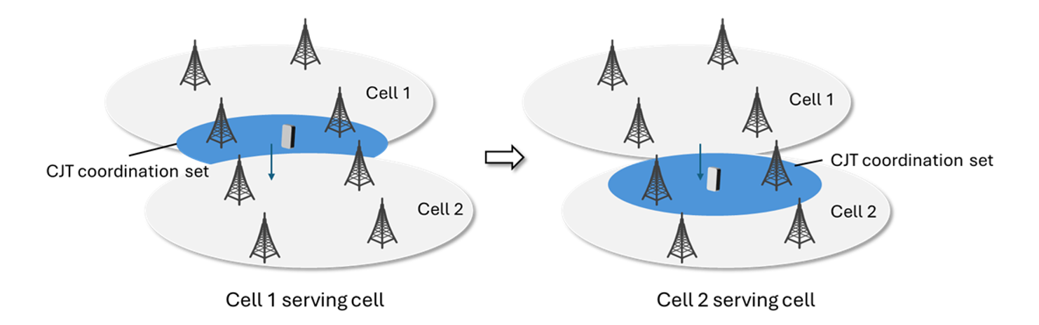
Figure 2. CJT coordination set and cell boundaries as supported in 5G-NR
The above issues can be circumvented in 6G via dynamic CJT coordination set adaptation. For 6G, a framework where a CJT coordination set can incorporate TRPs across different cells can be illustrated in Figure 3. As the UE moves within the coverage area of cell-2, the serving cell can be updated from cell-1 to cell-2, while still receiving transmissions from TRPs in cell-1 and cell-2. Hence, there is no interruption to the UE’s traffic and the UE benefits from having a larger and dynamically adapted CJT coordination set that includes TRPs in cell-1 and cell-2.
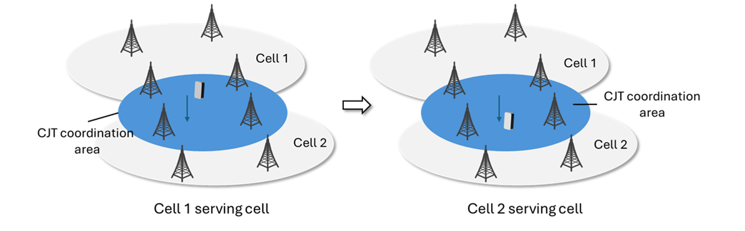
Figure 3. CJT coordination set and cell boundaries as envisioned for 6G
Dynamic CJT coordination set adaptation is supported by updating the CJT coordination set via the PHY-layer DL control channel (termed PDCCH). For low-/mid-bands (under 6 GHz, termed FR1) and the lower half of FR3 (around 7-15 GHz) where digital beamforming is used, each TRP is associated with a port-group where a port-group comprises all the antenna ports within the TRP. The CJT coordination set, therefore, comprises a set of port-groups wherein a Port-Group Indicator (PGI) is assigned to each port-group. For mmWave and the upper half of FR3 (around 15-24GHz) where analog beamforming is used from each TRP, the CJT coordination set comprises a set of beam indicators (termed Transmit Configuration Indicator or TCI state). Here, each TRP can be associated with a large number of beams. In this sense, a beam for mmWave is analogous to an antenna port for low-/mid-band.
To assist NW in updating the CJT coordination set to a UE, the UE measures the reference signals (RSs) specific to the PGI or TCI states. Based on the measurement report from the UE, the NW can signal a “new” or “updated” CJT coordination set to the UE. Evidently, dynamic CJT coordination set adaptation transcends the limitation artificially imposed by cell boundaries. The interruption time is removed by avoiding cell switch –thereby offering a truly seamless access user experience unlike the legacy mobility procedures in 5G NR.
To demonstrate the benefit of dynamic CJT coordination set adaptation, system-level simulation (SLS) is performed for the scenario in Figure 4 with 7 cells (each cell includes 3 TRPs). A UE moves across boundaries between different cells. Here, 2GHz carrier frequency with 10MHz channel bandwidth is assumed with the Dense Urban deployment scenario. Each TRP utilizes a 16-port 2D active antenna array. The UE, equipped with 4 receive antennas, moves at 120kmph speed and, depending on the channel condition, receives up to 4 layers. Compared with the performance of a static CJT coordination set based scheme, the results in Figure 4 depict up to 9% gain in average User Perceived Throughput (UPT) with 2-slot processing latency.
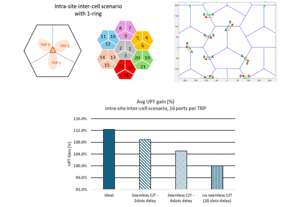
Figure 4. Simulation scenario for dynamic (PHY-level) coordination set adaptation and the SLS results
6G CJT: Channel State Information (CSI) Acquisition
To attain the benefit from CJT, the NW performs joint beamforming across multiple TRPs. In time division duplex (TDD), the channel reciprocity between DL and uplink (UL) channels can be exploited through estimating UL sounding reference signals (SRS) as long as the SRS can be reliably received at the TRPs. However, in frequency division duplex (FDD), the NW has to rely on UE feedback to assist NW in beamformer calculation. Furthermore, even for TDD, CSI acquisition via the CSI feedback is occasionally needed when the channel reciprocity could not be guaranteed due to poor SRS coverage and/or calibration impairments across TRPs. This necessitates CSI feedback as a means for facilitating joint beamforming across TRPs.
In Rel-18 5G NR, CSI feedback based on high-resolution Type-II codebook extended for CJT operation was specified. This extension accommodates joint coherent beamforming across spatially separated active antenna panels and dynamic subset selection within the CJT coordination set. However, the design was cumbersome and can be further streamlined for 6G to simplify implementation and improve performance.
First, several aspects should be considered in CSI reference signal (CSI-RS) measurement and CSI feedback where each TRP utilizes 2D active antenna array and its associated CSI-RS. As mentioned previously, each TRP is associated with a port-group. The spatial correlation properties of antenna ports within a port-group and across different port-groups, as well as the frequency selectivity of the composite channel need to be accounted especially for CSI codebook design. To minimize CSI feedback overhead, the spatial-domain (SD) components need to be selected per port-group while the frequency-domain (FD) components are common for all port-groups. Further enhancement for 6G can include selecting the SD components in a layer-specific manner. Moreover, AI-enabled CSI feedback can significantly reduce the feedback overhead and provide extensible solution for different antenna architectures – thereby offering a future-proof design for future 6G CJT deployments.
Second, for a given CJT coordination set, a CSI feedback instance should also include a recommended subset selection since not all the TRPs in the CJT coordination set can transmit sufficiently strong signals to the UE at a given time. This allows the NW to avoid wasting unnecessary resources for downlink transmission and increasing inter-cell interference. Therefore, only the beamforming information associated with the recommended subset of port-group(s) is reported to the NW.
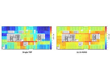
To demonstrate the benefit of CJT (equipped with CJT CSI feedback) over a single TRP, SLS is performed assuming 3.5 GHz carrier frequency with 20 MHz channel bandwidth and the Urban Macro deployment scenario. Each TRP utilizes a 64-port 2D active antenna array. The UE, equipped with 4 receive antennas, moves at 3 kmph speed and, depending on the channel condition, receives up to 4 layers. FTP traffic model is assumed. As evident in Figure 5, CJT (with 5G CJT CSI and a prospective streamlined design for 6G) offers up to 40% gain in average UPT compared with the performance of single TRP.
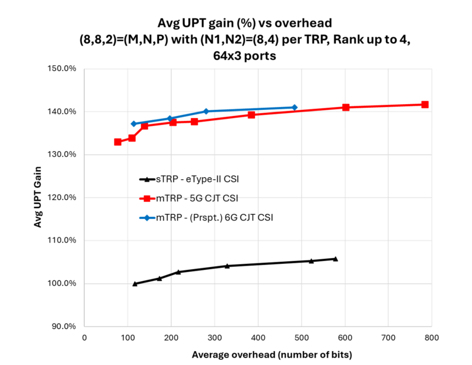
Figure 5. SLS results demonstrating the benefit of CJT (equipped with CSI) over single TRP
6G CJT: UE-Assisted Calibration
For CJT transmission across non-collocated TRPs where an on-site self-calibration is infeasible, UE-assisted calibration feedback has been specified in Rel-19 5G-NR. This comprises reporting inter-TRP delay offset, frequency offset, and (for TDD) downlink/uplink phase offset. The three schemes are to aid or assist the NW in calibrating any frequency, time, or phase mismatch among TRPs within the CJT coordination set. These mismatches are caused by differences in propagation delays between the TRPs and the UE, as well as hardware impairments within the TRPs and the UE. Once CJT calibration is performed at the NW, the NW can efficiently perform joint (coherent) beamforming across TRPs within the CJT coordination set based on the received CSI feedback and/or SRS measurement.
The UE-assisted calibration feedback specified in 5G offers a good starting point to develop a streamlined and enhanced version for 6G – especially tailored to more demanding needs for the new 6G FR3 frequency bands.
Delay offset reporting
As CJT collaboration area becomes wider, composite delay spread across TRPs can exceed cyclic prefix (CP) length of the CP-OFDM waveform. There are mainly two factors that can affect composite delay spread across TRPs: 1) timing alignment error (TAE) and 2) propagation delay difference across TRPs. The maximum timing alignment error (TAE) is typically around 65 ns [1] after GPS time/frequency synchronization, which is much smaller than a CP length. However, propagation delay difference across TRPs can vary depending on the locations of UE and the TRPs. When the composite delay spread across TRPs exceeds a CP length, inter-symbol interference (ISI) will occur which is detrimental for CP-OFDM. Therefore, two use cases of delay offset reporting can be considered:
Figure 6 shows an example of power delay profile (PDP) for each of the two use cases. For use case 1, a UE can be configured to measure CSI-RS transmitted from each TRP to estimate the power delay profile and delay offset/spread per TRP. The UE can then report a subset of TRPs with delay spread not exceeding CP via a 1-bit indicator per TRP. For use case 2, a UE can be configured to report per-TRP delay offset and spread with respect to a reference TRP. This enables the NW can compensate for excessive delay offsets resulting in ISI in order to fit the compensated composite delay spread within CP.
Therefore, two parameters per TRP can be reported: the first is associated with delay offset and the second indicates whether the delay spread exceeds CP or not. Then, the NW can compensate for the delay offset for each TRP and, if necessary, exclude some TRP(s) so that the composite delay spread is within CP.
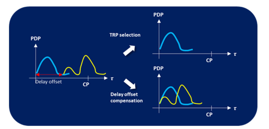
Figure 6. Two use cases of delay offset reporting
To demonstrate the benefit of such delay offset feedback, a three-sector CJT scenario is simulated, where each sector is located in a different site, as depicted in Figure 7. The Dense Urban scenario with 500m inter-site distance and 2GHz center frequency with 10 MHz channel bandwidth are assumed. Each TRP is equipped with a 16-port 2D active antenna array. The UPT results for both use cases are depicted in Figure 8. It can be observed that the inter-TRP CJT calibration (CJT-C) delay offset feedback offers 2.5 to 3 times average UPT. It can also be observed that a near-ideal performance can be attained with only 5-bit delay offset quantization. In summary, such massive gain can be obtained with a small cost.
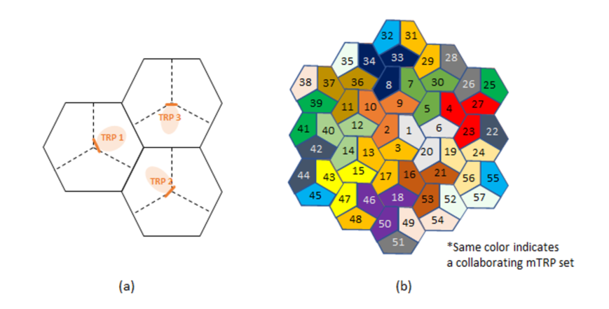
Figure 7. (a) Coordination set composed of three inter-site sectors (b) cell layout for SLS evaluations
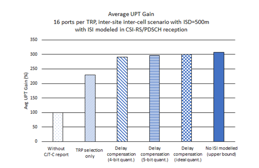
Figure 8. UPT comparison: 1) without CJT-C report, 2) with CJT-C report, TRP selection only (use case 1), and 3) with CJT-C report, delay compensation, w.r.t. quantization bits (use case 2)
Phase offset reporting for TDD DL/UL reciprocity
In TDD, a common approach to acquire DL CSI is to measure sounding reference signals (SRS) transmitted from a UE. By exploiting channel reciprocity, this UL channel measurement can be used for DL CSI calculation. However, due to RF impairments at transmitter and receiver, such an approach requires periodic calibration among receive and transmit antenna ports at the NW. For this reason, the NW utilizes an on-board module to calibrate its receiver and transmitter antenna ports. The on-board calibration mechanism can be done by NW implementation in a self-contained manner. However, extending such mechanism across multiple non-collocated TRPs would require over-the-air (OTA) signaling among the TRPs. Therefore, without any assistance from the UE, each TRP is expected to perform its own on-board calibration – thereby resulting in different post-calibration residual phase offsets across different TRPs. As shown later, this would result in a significant throughput loss.
To assist the NW in this otherwise daunting task, the UE first transmits a one-port SRS so that each TRP can measure the respective UL channel. This measurement is used to derive a matched-beamformer for a one-port beamformed CSI-RS transmitted to the UE. This essentially removes any effect from the DL channel and leaves out the residual DL/UL phase offset for the TRP. The UE then measures the beamformed CSI-RS, calculates, and subsequently reports the DL/UL phase offset for each of the TRPs. The UE can report either one phase offset per TRP for the entire channel bandwidth (‘wideband’) or for each sub-band within the channel bandwidth (‘sub-band). Equipped with this UE feedback, the NW can compensate for the differences in DL/UL phase-offset across the TRPs.
To demonstrate the benefit of such DL/UL phase offset feedback, the same setup depicted in Figure 7 is simulated. In addition to the DL/UL phase offset from RF impairments, we add TAE at each TRP (as described above for delay offset feedback) which introduces a linear phase offset ramp across the channel bandwidth. Figure 9 depicts the UPT gain when the UE reports the DL/UL phase offset for each TRP – both wideband and sub-band. It can be observed that for the smaller maximum TAE (33 ns), wideband and sub-band feedback perform virtually the same. But for the larger maximum TAE (65 ns), sub-band feedback offers large gain over wideband while the gain of wideband over no-calibration is marginal.
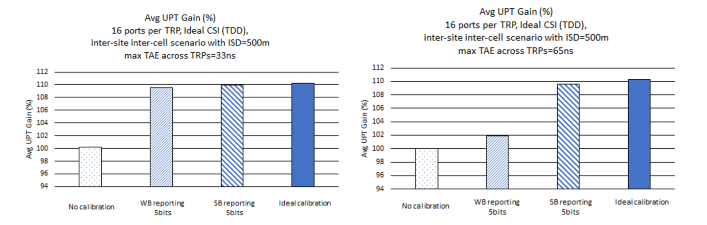
Figure 9. UPT gain over no calibration case for three methods: 1) WB phase-offset reporting, 5bit quantization, 2) SB phase-offset reporting, 5bit quantization, and 3) ideal calibration
Frequency offset reporting
There are two main factors that create inter-TRP frequency offsets across TRPs: frequency variations/errors caused by hardware impairments of different oscillators embedded in different TRPs, and Doppler shifts of channel environment caused by UE velocity. The inter-TRP frequency offsets can create channel phase drifts in time, so it can degrade the performance of CJT because the reported CSI becomes stale for an actual data transmission that usually is performed with a latency.
Similar to delay offset reporting, a UE can be configured to measure CSI-RS transmitted from each TRP, and the UE can measure inter-TRP frequency offset values with respect to a reference TRP. Once the inter-TRP frequency offsets are reported, the NW can compensate for the inter-TRP frequency offsets.
Conclusion
This article introduced CJT as the leading multi-TRP technology that promises massive capacity gain over the conventional single-TRP deployment. As the recent networks evolve more and more toward software-based architectures, the advent of active antenna system and cost-effective (yet low-impairment) backhaul solutions points toward CJT as the answer not only to the challenging requirements for 6G, but also to truly seamless user experience –unlike what legacy network providers can offer to-date.
Implementing CJT demands substantial investment from mobile network operators. Therefore, it is imperative that the upcoming 6G specification support the necessary component technology to maximize their return-on-investment. This article outlines three key components to ensure that the promise of CJT can materialize, namely dynamic CJT coordination set adaptation, CJT CSI feedback, and inter-TRP calibration feedback. Such components not only turn the promise of massive capacity gain into reality, but also expand the applicability of CJT to more challenging deployment scenarios such as inter-site CJT and new frequency bands.
There are other components we haven’t discussed which can be instrumental in realizing this goal. Examples include the use of artificial intelligence/machine learning (AI/ML) on network and UEs, energy efficiency consideration, and innovative antenna design surpassing the current 2D active antenna arrays. There are also scenarios beyond the incumbent Immersive Communications with untapped potential that can benefit from CJT. Examples include non-terrestrial networks (NTN) and its inter-working with their terrestrial network (TN) counterparts, massive IoT infrastructure, and even integrated sensing and communications (ISAC). Although this is wishful at present, whenever/wherever a multitude of transmit/receive nodes are available, CJT could be applicable. New scenarios for CJT could imply new challenges which would trigger additional research efforts, potential 6G specification enhancements, and, ultimately, new market opportunities for 6G.
References
[1] 3GPP Technical Specification, TS 38.104 v19.0.0, “NR; Base Station (BS) radio transmission and reception.”