Communications
Reconfigurable Intelligent Surface (RIS) and Factors Influencing Its Role in Future Networks
Background
One of the key efforts in the 5G era is to tap into vast chunks of the spectrum at high-frequency bands and make them suitable for wireless mobile communication. Technologies like 3D and hybrid beamforming were developed in that course. As a result, the millimetre-wave frequency bands, termed as FR2 by 3GPP, are recently put to commercial use across various global markets. The wide-spread usage of FR2 bands is hindered by the physical characteristics of these frequencies. The high propagation losses and heavy penetration losses incurred at these frequencies mean that that are highly suitable for use only if there is a line of sight propagation path between the transmitter and the receiver. However in real life deployment scenarios, this cannot always be guaranteed. One way to overcome this limitation and make the communication possible in “no line of sight” scenarios is the usage of repeater nodes between the transmitter and the receiver. A repeater is an active element where in it receives the signal from the transmitter, amplifies and repeats it towards the intended final receiver. This can compensate for the propagation and penetration losses incurred by non-line of sight propagation. However, repeaters comprise expensive RF chains, consisting of signal converters, filters, mixers and power amplifiers. Hence it is not an attractive option for wide-scale deployment.
RIS (Reconfigurable Intelligent Surface)
Since one of the future directions of Beyond 5G systems is to explore the usage of higher and higher frequency bands, there needs to be an alternative mechanism to overcome the transmission losses at high frequencies. At this juncture, reconfigurable intelligent surface (RIS) is being evaluated as one of the key components to achieve a smart radio environment. An RIS consists of low-cost passive reflective elements such as printed dipoles. Each of these elements can induce a programmable phase shift to the incident electromagnetic wave, which enables passive beamforming to improve the received signal power. An RIS when efficiently controlled, helps to align the signals at the receiver, resulting in a controllable radio environment. Thus, RIS can increase the beam-forming gain of a massive-MIMO system, by acting as a reflector of the original beam from the transmitter and changing its course to the receiver. RIS being comprised of passive elements cannot outperform a classical repeater. However, the lower cost and higher energy efficiency make them an attractive alternative.
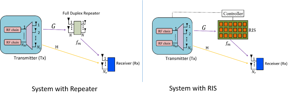
Figure 1. Full duplex repeater (left) used to help with coverage in comparison with RIS (right) used for the same purpose.
Further, we briefly cover a few system level aspects impacting practical deployments, based on our recent research.
Joint Optimization of Tx and RIS [1]
RIS being an array of passive reflective elements needs an intelligent controller algorithm to efficiently use it. Consider a simple system (Figure-1) with
(a) A transmitter equipped with Nt transmit antennas and NRF RF chains (Usually NRF < Nt and hence the best subset of Nt to
be used for transmit beam forming needs to be chosen by the transmitter),
(b) A receiver with N_r receive antennas and
(c) An RIS with N passive elements and a controller that shall be configured by the transmitter
The objective of RIS is to ensure a better reception for the receiver than what it would have had without RIS. Unlike a real base station, RIS does not have the ability to receive and process the CSI (Channel state information) report of the end receiver. So the transmitter has to jointly optimize both the link between transmitter and RIS (i.e. the transmit beamforming configuration between Tx and RIS) and the reflected link between RIS and Receiver (i.e. the passive beamforming configuration to apply on the RIS).
Technically transmitter needs to try all possible combinations of Tx beamforming antennas + RIS passive beam-forming configurations and identify the optimal configuration based on the feedback received from the receiver for each combination. This is a non-convex problem and hence computationally very expensive and highly delay prone.
In [1] and [2], we have evaluated these aspects. Here we have discussed a multi-antenna system, in which a subset of antennas are selected for the transmit beamforming, and a corresponding RIS beamforming configuration is selected. We have evaluated it to find the best combination using both optimal and low complexity methods. We proposed a simplified method based on alternating optimization approach (AOBSS). We compared its performance versus the manifold optimization method (MOBSS) and an SDR (Semi Definite Relaxation) method ([4]) in the literature (SDR needs NRF=Nt).

Figure 2. The average SNR as a function of distance between transmitter and receiver
Figure 2 plots the average SNR as a function of distance between transmitter and receiver. The performance gain with RIS usage is significant. Complexity comparison of these methods is as below.

Table 1. Complexity comparison
For typical system parameters, significant benefit in complexity can be observed with the proposed method, while the performance is very close to the most complex method. Most of the concepts discussed in this paper for antenna selection are applicable for beam selection in millimetre wave systems as well.
Placement of RIS [3]
While we can show significant gain in signal power and coverage with the use of RIS in a single link and experimental setup, it is not that easy to capture all the gain in a real network deployment comprising of multiple receivers scattered across the cell and each having a different propagation environment with respect to the transmitter. Thus placement and deployment of RIS in the cellular system plays an important role in taking full advantage of controlled radio environment. Our work in [3] covers a few important aspects in the placement of RIS.
We modelled various aspects of cellular system and RIS in a system level simulator at millimetre wave band and modelled the blockages using Poisson process. Various configurations of RIS like the number of elements, their spacing, orientation etc were also modelled (Figure 3).

Figure 3. Blocked region, hypothetical RIS placement grid in a 3-hexagonal cell sectors in an urban cell.
In one approach we identified the favourable position for RIS as the location that maximizes the average SINR (Signal to Interference-plus-Noise ratio) observed by all the users in the cell. In a variant approach, we also identified the favourable position of RIS as the one with shortest distance from the blocked region while maximizing the average SINR. Performance of various approaches can be seen in Figure 4. We observe that there is some gain in the SINR with any type of placement of RIS in the network. While the proposed RIS placement with first best position for each location of blockage performs the best. We tried to evaluate the situation that the 1st best position is not available for placement of RIS in some locations, we chose the second or third best position in such cases. By that order, the performance of second and third best positions follow the SINR distribution of first best position. Detailed modelling aspects and simulation settings are shown in [3]
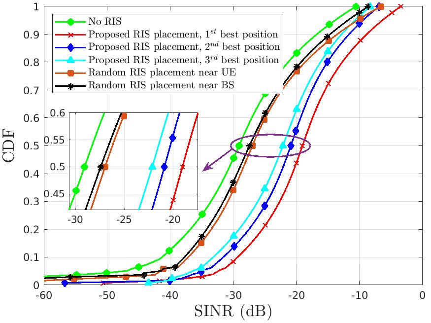
Figure 4. SINR CDF for UMI layout with ISD=200 m, affected with blockages.
Future Outlook
While we observe gains in average SINR and coverage of the cell using RIS, there are more aspects that need careful consideration. First of such aspects is ease of deployment, maintenance and cost. Beyond that, the aspects of interference need to be considered. Configuration of an RIS in one sector of the cell can reflect the signal of the undesired user towards unintended direction, resulting in severe intra-cell and inter-cell interference. Likewise RISs can reflect signals beyond one licenced band of an operator, when adjacent bands are being used by different operators. In such cases, the RISs controlled by one operator can influence the signals of other adjacent band used by different operator. This would require inter-operator coordination for using RIS within a geographical area. Further, such a coordination may also need a regulating authority to define the usage.
While there is a need for further research in the aspects highlighted above, RIS can be beneficial to the millimetre wave and higher frequency bands in improving the cell coverage, which is one of the main concern with the present FR2 deployments.
Disclaimer:
The views and opinions expressed in this article are solely those of the authors. These do not necessarily represent those of Samsung Research and its affiliates
Link to the paper
[1] https://ieeexplore.ieee.org/document/10018901[2] https://ieeexplore.ieee.org/document/9417367
[3] Accepted for IEEE ICC-2023. https://icc2023.ieee-icc.org/
References
[1] R. Sarvendranath, Ashok Kumar Reddy Chavva and E. G. Larsson, "Optimal Antenna Selection and Beamforming for an IRS Assisted System," in IEEE Transactions on Wireless Communications, doi: 10.1109/TWC.2023.3235835.
[2] R. Sarvendranath and Ashok Kumar Reddy Chavva, "Low-Complexity Joint Antenna Selection and Beamforming for an IRS Assisted System," 2021 IEEE Wireless Communications and Networking Conference (WCNC), Nanjing, China, 2021, pp. 1-6, doi: 10.1109/WCNC49053.2021.9417367.
[3] Ankur Goyal, Anusha Gunturu, Ashok Kumar Reddy Chavva, Hanjin Kim, Huiwon Kim and Seunghyun Lee, “Placement of Reconfigurable Intelligent Surfaces in Urban Cell For Improved Coverage - A Practical Approach,” Accepted in 2023 IEEE International Conference on Communications (ICC), Rome, Italy, 2023 May.
[4] Q. Wu and R. Zhang, “Intelligent reflecting surface enhanced wireless network: Joint active and passive beamforming design,” in Proc. Globecom, Dec. 2018, pp. 1–6.