Communications
RAN-CN Convergence Towards the Next-Generation Networks
The Need for a More Flexible Network Architecture
6G system is expected to be a platform providing hyper-connectivity to everyone and everything in the 2030’s. Along with continuous improvement of 5G services, new 6G services with various requirements are emerging, such as truly immersive extended reality, high-fidelity mobile hologram, collaborative robots, and digital replica. In order to realize such new services, the 6G network should be designed to provide more efficient configurations across Radio Access Network (RAN) and Core Network (CN), suitable to the requirements of each service, based on advanced flexibility and agility.
The network virtualization and cloud computing technologies make configuration and rearrangement of network functions (NFs) easier. To this end, some level of flexibility is already supported in 5G along with the virtualization trend. However, the definition of NF and the network protocols strictly separate the RAN and the CN and this limits the levels of flexibility and efficiency provided by the network. In 6G, a new approach is needed to provide more flexibility in network deployment where the RAN and the CN functions can be converged in the same platform and optimized together according to the requirements. We address both the control-plane (CP) and the user-plane (UP) aspects of the 6G converged RAN-CN architecture in this blog post.
6G Control Plane Design: Flexibility and Agility To Be Cloud-Friendly

Figure 1. Network architecture
End-to-End Service-Based Architecture (E2E SBA)
In line with the cloudification and virtualization trends, the 5G system introduced service-based architecture (SBA) to transform the CN architecture to be cloud-friendly. Within the SBA, NFs exchange information through a common interface, called service-based interface (SBI). However, this change has not been applied to the RAN due to the logical barrier between the RAN and the CN. In 5G, centralized unit – control plane (CU-CP), which acts as a brain of the RAN, has to be connected to access & mobility function (AMF) via peer-to-peer (P2P) interface to communicate with other CN NFs, as shown in Figure 1 (a). Similarly, signaling from user equipment (UE) must pass through the peer-to-peer connections from DU to CU-CP and then to AMF in order to reach other NFs. The pre-defined anchor points from peer-to-peer communication causes unnecessary transmission overhead and makes deployment of other NFs dependent on the location of CU-CP and AMF, which are the anchor points to travel over.
To address these issues, we introduce an end-to-end SBA, where RAN can communicate directly with other NFs via SBI, a common interface of CP entities, as shown in Figure 1 (b). In the architecture, all CP entities on the network are connected to each other through single hop SBI communications. Therefore, any CP entity can be placed in a location suitable for its purpose more independently from the location of the other NFs, thus providing improved deployment autonomy. In 6G distributed cloud environments with various types of clouds (e.g., central cloud, edge cloud, on-premise cloud, etc.), this property will be highly beneficial to utilize the cloud resources efficiently.

Figure 2. Arrangement of functionalities in the network
Purpose-Oriented Network Function Over RAN and CN
Another design principle for 6G CP architecture could be designing an entity in a purpose-oriented way, i.e., dedicate specific service/purpose to one NF. It is expected to give advantages in deploying, operating, and managing the services for each purpose by minimizing the dependencies among entities.
Figure 2 shows an example of the purpose-oriented NF configuration. Each NF performs most operations for a specific purpose of service independently and directly configures the other NFs and UEs. In case of mobility management, for example, a number of NFs, e.g., SMF, CU-CP PCF, and AMF, are involved in the mobility-related operations in the 5G architecture. In the proposed architecture, however, we redefine the mobility management function (MMF) over traditional RAN and CN domains. In such a case, mobility-related operations are mostly processed within the single entity, and only the limited number of essential signaling messages are exchanged with other NFs via SBI directly. Introduction of a new service on mobility, e.g., AI-based mobility optimization, has influence only on the MMF in this example.
This type of NF configuration reduces the computational overhead and latency for the singling, and the numerical results show that the completion time of control procedures and the number of required signaling messages are reduced by up to 27% and 45%, respectively.
E2E AI Operation and Unified Storage
The information related to each service is stored in multiple NFs across RAN and CN in the conventional architecture, and AI function needs to collect information from the multiple NFs to comprehensively analyze and optimize the service. We assume that the separation of AI functions in RAN and CN domains, e.g., RAN intelligent controller (RIC) in O-RAN alliance and network data analytics function (NWDAF) in 3GPP, will be more blurred in this architecture, and it will enable better cross-domain optimizations by AI. The E2E SBA architecture addressed above will allow AI functions to easily obtain all information on each service by directly accessing the NF in charge of the service if needed.
The introduction of unified storage can also be considered for a more AI-friendly environment. The unified storage is shared by the entire network, which stores all network configurations and dynamic information for UE communication. As the authorized NF modifies the information, the information is immediately updated throughout the network, and the AI function can obtain the latest information without affecting the operations of NFs by accessing the storage. Besides, load balancing among NFs and scaling-in/-out of NFs can be conducted more flexibly and efficiently since data is managed in the unified storage.
6G User Plane Design: Flexibility for Optimization
Compared with the CP design discussed above, the UP design generally puts more emphasis on its packet processing performance. However, providing various use cases is another key issue to pursue, and hence, the 6G UP design should provide the flexibility to achieve the best performance for each use case.
Flexible User Plane Reference Architecture for 6G
Instead of a clear distinction of UP functionalities between the RAN and CN NFs adopted in the conventional 5G architecture, we define an element unit of UP function, called sub-function (SF), which composes a UP NF, i.e., 6G-UP. That is, each 6G-UP is realized by the combination of multiple SFs as needed regardless of whether they belong to RAN or CN functionalities in the conventional 5G architecture. The SF can also contain new functionalities to deal with new requirements or services in the future network. In this approach, network operators are allowed to flexibly determine and realize the UP deployment according to requirements such as deployment environments, quality-of-service (QoS) requirements of target services and specialized hardware to use (e.g., GPU and smart NIC). The 6G-UP(s) can be placed anywhere as needed, either close to the cell site (edge cloud) or in the central cloud.
Specialized User Plane Architecture with Merged UP
In order to further optimize the UP in 6G network, we define a special type of 6G-UP, referred to as merged UP (M-UP), which includes both the RAN-related SFs, especially with the higher-layer functionalities of 5G RAN, and the CN-related SFs within a single NF. Figure 3 shows a UP architecture design based on M-UP. M-UP has UP interfaces to data network (DN) and enhanced DU (eDU), which includes lower-layer UP functionalities of 5G RAN, at the same time. Also, M-UP has a unified CP interface for the control of its operations. With this simpler architecture, we expect to achieve reduction in packet processing load due to the reduced number of interfaces between NFs and the increased efficiency in protocol operations with the elimination of duplicated operations. This architecture based on M-UP is especially beneficial for the applications with requirements of extremely high data rate and low latency in 6G, because of the reduced burden of packet processing for each packet from the extremely large amount of packets of the application to be processed in time.
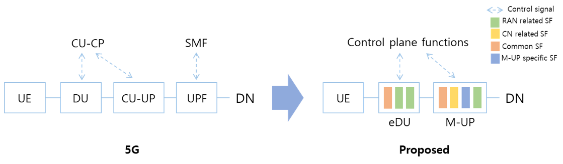
Figure 3. UP architecture with M-UP
M-UP may involve some newly introduced SFs of functionalities, which are specially optimized for the merged deployment. For example, M-UP can directly map IP packets to data radio bearers (DRBs) for QoS treatment instead of a two-step mapping from IP packets to QoS flow in user plane function (UPF) and from QoS flow to DRB in CU-UP in 5G architecture. Also, M-UP can directly insert QoS parameters in layer-2 header while the parameters should be inserted and extracted twice in UPF and CU-UP in 5G. Moreover, M-UP can perform the fewer interface-related operations because of the simpler architecture.
We have evaluated our M-UP based UP architecture design in terms of the UP packet processing load and system throughput based on our open source based testbed system using Open5GS (v2.2.9) and UERANSIM (v3.2.0). Figure 4 (a) shows the average consumed CPU cycles per packet, where we observe that our design can significantly reduce the processing load of every UP packet thanks to the increased protocol efficiency explained above. As a result, we can see that the system throughput can be also improved under a constraint of available amount of computing resources, as shown in Figure 4 (b).
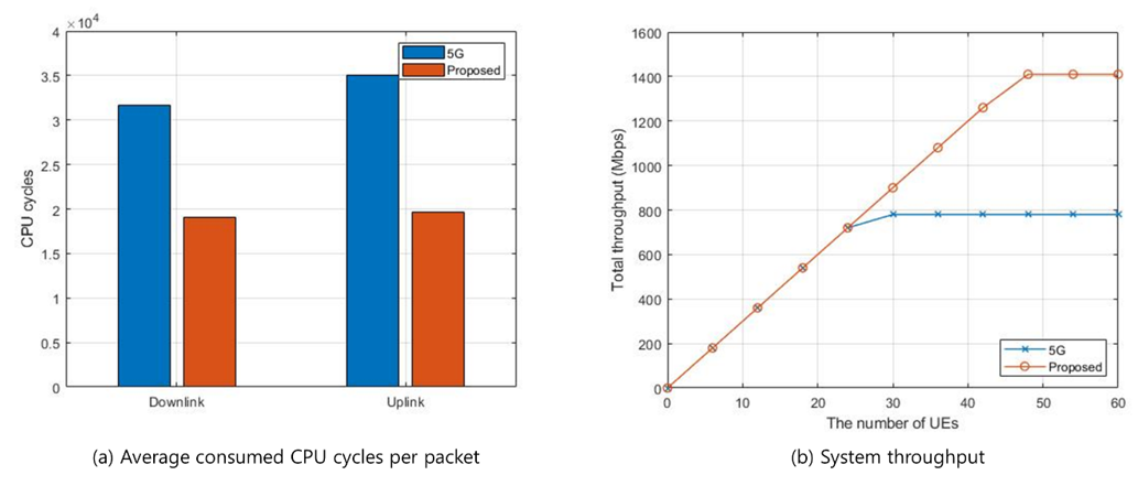
Figure 4. Performance evaluation results for 5G and M-UP-based architecture
Concluding Remarks
The main contribution of this blog post is to identify the limitations and constraints of the conventional architecture and to provide design principles of the 6G network architecture suitable for cloud environments with improved flexibility. Next time, we will discuss further details of how to define network entities and configure slices and sub-networks within the proposed RAN-CN converged architecture.
References
[1] J. Choi, N. Sharma, S. S. Gantha, V. Mandawaria, J. Cha, D. Kim, J. Jung, J. Lee, and S. Choi, "RAN-CN Converged Control-Plane for 6G Cellular Networks," in Proc. IEEE GLOBECOM 2022, Dec. 4-8, 2022.
[2] J. Cha, Y. Moon, S. Cho, D. Kim, J. Choi, J. Jung, J. Lee, and S. Choi, "RAN-CN Converged User-Plane for 6G Cellular Networks," in Proc. IEEE GLOBECOM 2022, Dec. 4-8, 2022.
[3] Samsung Research, "Samsung 6G white paper: The next hyper-connected experience for all," July 2020. Available: https://research.samsung.com/next-generation-communications
[4] NGMN, "Service-based architecture in 5G," Jan. 2018. Available: https://www.ngmn.org/publications/service-based-architecture-in-5g.html
[5] H. Viswanathan and P. E. Mogensen, "Communications in the 6G Era," IEEE Access, vol. 8, pp. 57,063–57,074, 2020.
[6] V. Ziegler, H. Viswanathan, H. Flinck, M. Hoffmann, V. Räisänen, and K. Hätönen, "6G Architecture to Connect the Worlds," IEEE Access, vol. 8, pp. 173,508–173,520, 2020.
[7] "Open5GS: A C-language Open Source implementation for 5G Core and EPC". Available: https://github.com/open5gs/open5gs
[8] "UERANSIM: Open source 5G UE and RAN (gNodeB)". Available: https://github.com/aligungr/UERANSIM