Communications
Building ISAC in Practice: From Raw Radio Signals to AI-Driven Sensing
1. Introduction
In modern mobile networks, the base station (BS) continuously estimates the radio channel to each user equipment (UE) to support operations such as beamforming, link adaptation, and scheduling. This channel state information (CSI) carries more than link quality: walls, doors, and moving people all shape the paths a signal takes, so changes in the CSI over time reveal what is happening in the surroundings. Integrated sensing and communication (ISAC) exploits this to let the network sense its environment with the same signals and hardware it uses for communication [2]-[4]. We consider the UE-to-BS uplink bistatic configuration, in which the BS receives uplink reference signals from a UE and uses the resulting CSI both for communication and for sensing people at a building entrance.
ISAC is being studied in 3GPP for both 5G-Advanced and 6G [5], [7]. Because cellular networks already provide wide-area coverage, wideband radios, and massive multiple-input multiple-output (MIMO) arrays, sensing added in software can become available wherever the network is, without cameras or dedicated radar hardware. The uplink bistatic mode is particularly attractive for early deployment, since it requires neither full-duplex operation nor new hardware. In this work, we target presence and entry/exit detection on a commercial virtualized radio access network (vRAN): a fixed UE placed indoors at a building entrance transmits uplink reference signals to a commercial 64-transmit/receive (64TR) massive MIMO base station across an outdoor street, and the system detects in real time whether anyone is present near the entrance and whether people are entering or exiting.
Moving from concept to a working system, however, raises challenges at two levels. At the signal level, CSI produced for communication is not radar data. The UE is synchronized to the BS only within communication tolerances, and its residual timing and phase offsets, harmless for communication, appear as false range and Doppler variation when CSI is compared across symbols; together with sidelobes and strong static clutter, they bury weak human reflections. The resulting range-Doppler maps (RDMaps) also differ from natural images: their axes have physical meaning, multipath creates ghost copies of targets, and moving structures such as doors produce Doppler of their own. Apart from an empty scene, a person entering, a person leaving, and someone present nearby are difficult to tell apart in a single RDMap.
At the system level, full-band CSI amounts to hundreds of Mbit/s per UE and must be moved and processed in real time without burdening the radio access network (RAN). Moreover, frame-level outputs fluctuate, yet the reported state must remain stable while still following people as they pass. The remainder of this post introduces the system we built to address these challenges and validates it through experiments at two campus entrances, real-time operation on a commercial vRAN, and demonstrations to several mobile network operators.
2. Proposed System
2.1 System Overview
Figure 1 illustrates the receiver processing chain of our UE-to-BS bistatic ISAC system. The uplink signal transmitted by the UE passes through the receive (RX) front-end and channel estimation stages of the standard communication receiver. At the output of channel estimation, the processing splits into two paths. The upper path is the conventional communication path, where the CSI is used for operations such as scheduling and beamforming. The lower path, highlighted as the sensing block, reuses the very same CSI: a signal preprocessing stage converts it into a clean range-Doppler map (RDMap), and an AI-based event detection stage classifies the RDMap into target events such as a person entering or leaving, or someone being present nearby.
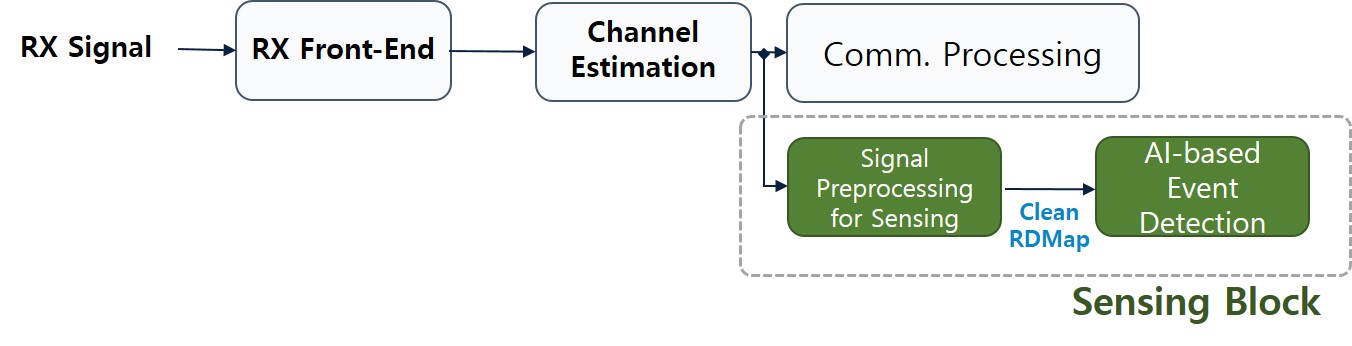
Figure 1. Overall receiver processing chain of the UE-to-BS bistatic ISAC system.
The key design principle is that sensing functionality is added to an existing communication receiver without any dedicated radar hardware or modification to the communication path. The communication processing itself is unaffected; the sensing block simply taps into what the receiver already produces, using uplink reference signal resources for sensing.
In the UE-to-BS bistatic configuration, the base station receives the uplink signal transmitted by a UE. This signal contains both the line-of-sight (LoS) (or otherwise dominant) component, which travels directly from the UE to the BS, and components reflected from surrounding objects such as people. From the RX front-end onward, communication and sensing share exactly the same hardware and the same signal.
Using the uplink reference signal, the receiver estimates the frequency-domain channel response, i.e., the CSI. From the communication perspective, this CSI supports uplink scheduling and link adaptation, as well as downlink beamforming through channel reciprocity. From the sensing perspective, however, the CSI is itself a snapshot of the environment. The distance to a reflector appears in the delay components of the channel, and its motion appears as symbol-to-symbol phase variation, i.e., Doppler.
The sensing block converts the CSI into an RDMap through the preprocessing described in Section 2.2 and detects events from it with the AI model described in Section 2.3. The RDMap is a two-dimensional map of Doppler velocity and bistatic range (in Figure 2, the horizontal axis is Doppler velocity and the vertical axis is bistatic range); the intensity of each cell indicates the energy reflected from objects at that range and velocity. Because the preprocessing aligns all paths to the LoS path, range is measured relative to the LoS path, which is why the range axis in Figure 2
2.2 Signal Preprocessing
Figure 2 shows the preprocessing chain with measured results at each stage, taken from an offline study using over-the-air measurements. A commercial Galaxy S25+ smartphone transmitted a 5G New Radio (NR) uplink reference signal over 100 MHz at 3.85 GHz to a 64TR Massive MIMO Unit (MMU) installed on a building at the Seoul R&D Campus; the UE was placed at the entrance of another building across the street, with pedestrians moving in between. This offline study uses the full received data, while the real-time system described in Section 2.4 uses a reduced subset.
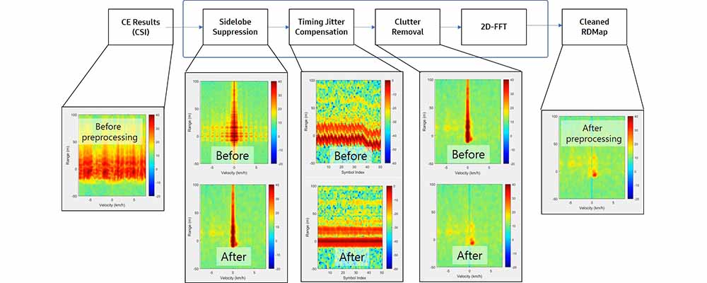
Figure 2. Signal preprocessing blocks and measured results at each stage.
The input is the frequency-domain CSI, a matrix of subcarriers by reference-signal symbols. An IFFT along the subcarriers and an FFT along the symbols turn it into an RDMap. Applying these transforms directly to raw CSI yields the leftmost map: energy is smeared across the velocity axis by timing errors, static clutter, and LoS sidelobes, and no target can be discerned.
Sidelobe Suppression
Finite bandwidth and a finite observation time produce sinc-shaped sidelobes around strong paths such as the LoS path; these sidelobes can be tens of dB stronger than human reflections. Windowing along frequency and time removes the resulting stripes at the cost of a slightly wider main lobe.
Timing Jitter Compensation
Although the UE is synchronized to the BS for communication, residual symbol-to-symbol timing fluctuations from its own oscillator and timing adjustments make the LoS range drift over the processing interval [2], [6], which smears energy along the Doppler axis and makes static objects appear to move. With the LoS path as a reference, the per-symbol offset is estimated and removed. Without this step, meaningful Doppler analysis is not possible in bistatic ISAC.
Clutter Removal
Walls, floors, and the LoS path form a strong ridge at zero Doppler. Removing this static component reveals the weak reflections beneath it; the strength of this removal must be tuned so that the subtle motion of a nearly stationary person is not removed with it.
The cleaned RDMap on the right reveals targets that were completely hidden in the raw map and is passed to the AI-based event detection block in Figure 1.
AI-based Event Detection
At first glance, an RDMap looks like an image, but it differs from natural images in ways that matter for model design. Learning-based methods have shown strong potential across wireless problems [1], yet in sensing their benefit depends on whether the inductive biases of the model match the physics of the radio channel.
What makes RDMap data different. Doppler carries absolute meaning: zero Doppler separates static from moving reflectors, and its sign distinguishes motion toward or away from the link, so a horizontal flip, a routine image augmentation, changes the label itself. Multipath creates weaker ghost copies of a target at longer bistatic ranges. Moving structures in the environment, such as ordinary and revolving doors, produce Doppler of their own that can resemble human motion. Finally, noise is always present: targets are weak, the noise floor varies with link conditions, and residual clutter remains after preprocessing.
Target events. The model distinguishes four states: enter (a person entering), exit (a person leaving), presence (someone nearby without passing through), and clear (no one present). The Doppler sign indicates whether the bistatic path is shortening or lengthening, but how this maps to entering or leaving depends on where the entrance lies relative to the UE-BS geometry. In practice, apart from the clear case, the four states are difficult to tell apart by eye in individual RDMaps. This is especially true at the entrance with the automatic revolving door, which starts rotating whenever someone approaches: as Figure 3 shows, presence, enter, and exit all produce energy spread over a similar span of range and Doppler, and the differences lie in subtle patterns that evolve over consecutive frames. This is precisely where a learned model is needed.
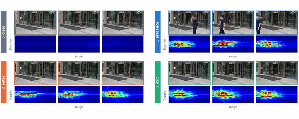
Figure 3. Camera frames (used only for labeling) and the corresponding RDMaps for the four states at the entrance with the automatic revolving door (range on the horizontal axis, Doppler on the vertical axis). Apart from the clear state, the RDMaps are difficult to distinguish by eye.
Design principles. Rather than describing a specific architecture, we highlight the principles that mattered most in practice. Decisions are made over short sequences of consecutive RDMaps rather than single frames. The meaning of the Doppler axis is preserved, and data augmentation is limited to transformations a real channel could produce. Because each site has its own static structures, moving doors, and residual clutter, the model learns the background of the deployment environment. For evaluation, we use held-out sessions, because random frame-level splits overestimate accuracy when consecutive frames are strongly correlated. Finally, the model is kept lightweight enough for real-time inference at the 200 ms update rate.
2.4 Integration into the RAN
A sensing chain that works offline must still fit within the radio resources, data paths, and computing resources of a commercial RAN, none of which were dimensioned with sensing in mind.
Reference signal period. We evaluated both dense and sparse sounding of the reference signal and confirmed that the difference in detection performance is marginal, so the sensing period can be relaxed without sacrificing detection.
Data volume. Full-band CSI is large. For a 100 MHz carrier at 30 kHz subcarrier spacing (3,276 subcarriers), 64 receive antennas, and 16-bit I/Q samples, it amounts to hundreds of Mbit/s for a single UE at typical sounding periods. While the offline study in Figure 2 uses the full data, the real-time system reduces it in two dimensions before it leaves the distributed unit (DU). In frequency, we keep only a small subset of subcarriers spread across the band; range resolution is unchanged, because it is set by the total bandwidth, and although the maximum unambiguous range shrinks, it remains far beyond the sensing area of about 100 m. In space, we use a subset of the receive antennas. Together, these steps reduce the data by more than an order of magnitude compared with full-band CSI from all antennas.
Stable real-time output. The model outputs a state every 200 ms, and individual outputs can fluctuate from one update to the next. Rather than reporting raw outputs, we apply post-processing with event-specific decision thresholds, which keeps the reported state stable while still following people as they pass, at the cost of a short delay.
System integration. Channel estimation runs on the MMU as it does for communication. The DU forwards the reduced CSI to an external server equipped with a GPU, which runs preprocessing, AI inference, and post-processing in real time. The system runs on a commercial vRAN, in which the DU is implemented as software on a general-purpose server. This allowed us to add the sensing data path through software updates alone, so that new versions could be deployed and tested on the live network quickly and easily. If the vRAN server itself is equipped with a GPU, the sensing function can share it with the RAN software [8], and the entire chain can run within a single platform. We instead built the pipeline to operate with an external GPU server so that sensing can also be added to existing deployments without GPU acceleration. The radio hardware is commercial and unmodified, and sensing needs no dedicated sensing signal or additional radio unit. Running inference on a separate server also keeps the sensing computational load off the RAN, so that it does not compete with communication processing, and the data reduction above keeps the forwarded data rate modest. Figure 4 shows the resulting configuration. Only event-level results are exposed to applications.
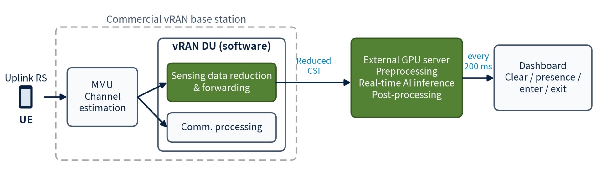
Figure 4. Real-time system integration: the DU forwards reduced CSI to an external GPU server for preprocessing, inference, and post-processing.
3. Implementation Results
3.1 Experimental Environment
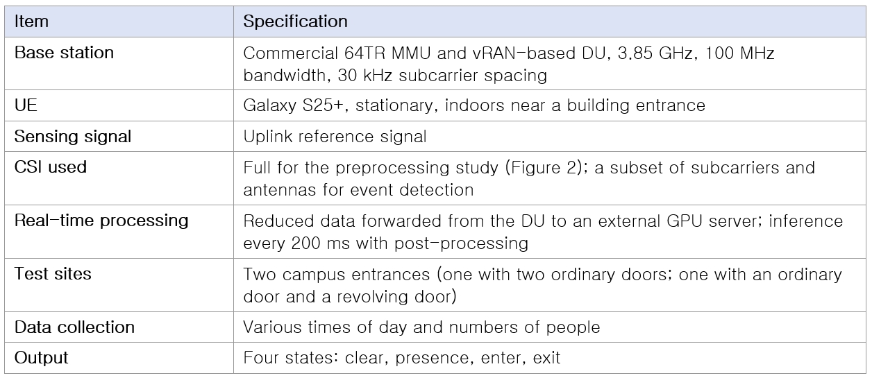
Experiments were conducted on our campus with a commercial smartphone and a commercial vRAN-based base station. Table 1 summarizes the experimental environment.
Table 1. Experimental environment
3.2 Entry and Exit Detection
A commercial smartphone (Galaxy S25+) was placed indoors in a fixed position near a building entrance, and a base station outside the building received its uplink reference signals. The smartphone stood in for a dedicated fixed sensing device or customer premises equipment (CPE), which would take this role in deployment without additional hardware. People walking through the entrance crossed the propagation paths between the UE and the BS; because the UE did not move, the geometry was stable, and changes in the RDMap could be attributed to the environment. Figure 5 shows one of the test sites: the UE was deployed indoors behind an entrance with a revolving door, and the MMU was mounted on the rooftop of a building across the street.
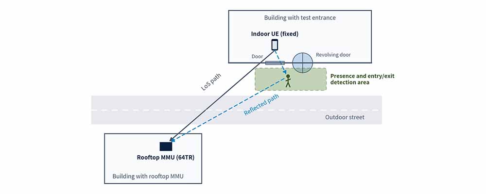
Figure 5. Test site layout: the UE deployed indoors at a building entrance with a revolving door, and the MMU mounted on the rooftop of a building across the street. Both the LoS path and paths reflected by people near the entrance reach the MMU.
We collected data at two entrances on our campus, covering different times of day and numbers of people. One entrance has two ordinary doors; the other combines an ordinary door with an automatic revolving door, which starts rotating whenever a person approaches and adds a Doppler signature of its own. Across both sites, the system consistently distinguished the four states, including at the entrance with the automatic revolving door (Figure 3), where the model had to separate a person walking through from a door that moves whenever someone is nearby. Such entry and exit events support occupancy management, building security, and energy control.
We also ran the same chain in real time with the live uplink of the UE (Section 2.4), displaying the detected state on a dashboard every 200 ms, so that the result could be seen changing as people walked through the entrance. This real-time system was further demonstrated to several mobile network operators; unlike the data collection on our campus, in which recorded data were evaluated offline, the demonstrations showed live inference results on site. Figure 6 shows the dashboard at the test entrance: as a person leaves the building, the detected state changes to exit, shown alongside the latest RDMap.
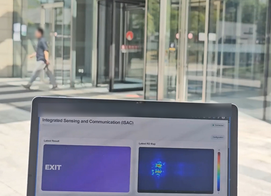
Figure 6. Real-time operation at the test entrance: the dashboard shows the detected state (exit) and the latest RDMap as a person leaves the building.
4. Conclusion
This post has presented a practical path to ISAC on a commercial vRAN-based 5G network. By reusing the uplink CSI that the receiver already produces, our system detects presence and entry/exit at a building entrance using only a base station and an ordinary UE, without additional radio hardware.
Key Contributions:
· Sensing on a commercial vRAN: sensing is added to a commercial vRAN-based network through software updates, reusing uplink reference signals on unmodified radio hardware, with inference on an external GPU server.
· A practical preprocessing chain for bistatic CSI: sidelobe suppression, timing jitter compensation, and clutter removal, validated on over-the-air measurements, turn unusable raw CSI into clean RDMaps.
· Validated in practice: experiments at two campus entrances, including one with a revolving door, real-time operation on a commercial vRAN, and demonstrations to several mobile network operators.
Future work will focus on two directions. The first is on-site learning. Because each site has its own static structures, moving doors, and residual clutter (Section 2.3), we aim to let the model adapt to a new location using data collected on site, so that the system can be deployed at new buildings without retraining from scratch. The second concerns operation at scale. When multiple UEs sense multiple locations within a cell, reference signal resources must be shared among the sensing links and with communication. This calls for a sensing-aware scheduler that decides which UEs to sound, how often, and when, for example by assigning sparse sounding to idle locations and dense sounding to active ones, building on our observation that detection performance is maintained even with sparse sounding. Privacy remains a design principle throughout: the system reports only clear, presence, enter, and exit states, contains no identifying information, and processes data at the edge.
References
[1] ] C.-X. Wang, M. Di Renzo, S. Stanczak, S. Wang, and E. G. Larsson, “Artificial intelligence enabled wireless networking for 5G and beyond: Recent advances and future challenges,” IEEE Wireless Commun., vol. 27, no. 1, pp. 16–23, Feb. 2020.
[2] V. V. Ratnam, M. Bayraktar, Y. Nam, C. Tarver, H. Chen, C. Qian, B. Yu, and C. Zhang, “Integrated Sensing and Communication (ISAC): New Monetization Opportunities for 5G and Beyond,” Samsung Research Blog, Dec. 2025.
[3] J. Shim, Z. Zhang, B. Yu, and H. Ji, “6G ISAC: Expanding the Value of Mobile Networks Beyond Connectivity,” Samsung Research Blog, Jun. 2026.
[4] F. Liu et al., “Integrated sensing and communications: Toward dual-functional wireless networks for 6G and beyond,” IEEE J. Sel. Areas Commun., vol. 40, no. 6, pp. 1728–1767, Jun. 2022.
[5] 3GPP TR 22.837, “Feasibility study on integrated sensing and communication,” 2024.
[6] V. V. Ratnam, H. Chen, H.-H. Chang, A. Sehgal, and J. Zhang, “Optimal preprocessing of WiFi CSI for sensing applications,” IEEE Trans. Wireless Commun., vol. 23, no. 9, pp. 10820–10833, Sep. 2024.
[7] 3GPP RP-251861, “New SID: Study on Integrated Sensing and Communication (ISAC) for NR,” Jun. 2025.
[8] Samsung Newsroom, “Samsung and Verizon Complete Successful ISAC Trial Over Virtualized Network at Global Sports Event,” Sep. 2026.