Communications
Streamlined, Efficient and Intelligent User Plane Design for 6G
Introduction
6G wireless networks are expected to improve on 5G across several key performance indicators, including latency, peak data rate, and connection density [1]. While much of the wireless industry's spotlight shines on new spectrum frontiers and advanced physical layer waveforms, the structural architecture of the network must evolve in tandem to prevent severe processing bottlenecks. With every new generation of wireless communication, the user plane has quietly evolved into one of the most critical components of the radio protocol stack. It is the user plane design that ultimately determines how efficiently user data is delivered, how much power mobile devices and base stations consume, and how well the network adapts to diverse service requirements.
In earlier generations, specifically 4G and 5G, the user plane architecture was characterized by rigid, layered protocol stack structures (such as SDAP, PDCP, RLC, and MAC) and reactive mechanisms. While these have served mobile broadband well, they are not well suited to 6G's tighter latency, energy, and processing requirements for services such as immersive communication and ultra-reliable autonomous systems. Scaling the existing stack to meet these demands is expected to introduce significant overhead, redundant processing stages, and higher computational energy costs.
To meet 6G's demands, the user plane is expected to undergo a paradigm shift toward a streamlined, efficient, and intelligent design. Current 3GPP standardization efforts for 6G are advancing towards this novel user plane paradigm, designed to manage 6G's extreme traffic demands while strictly respecting the stringent energy and processing constraints of future wireless ecosystems. This article will explore the foundational design principles and the early standardization work being undertaken to realize this next-generation user plane.
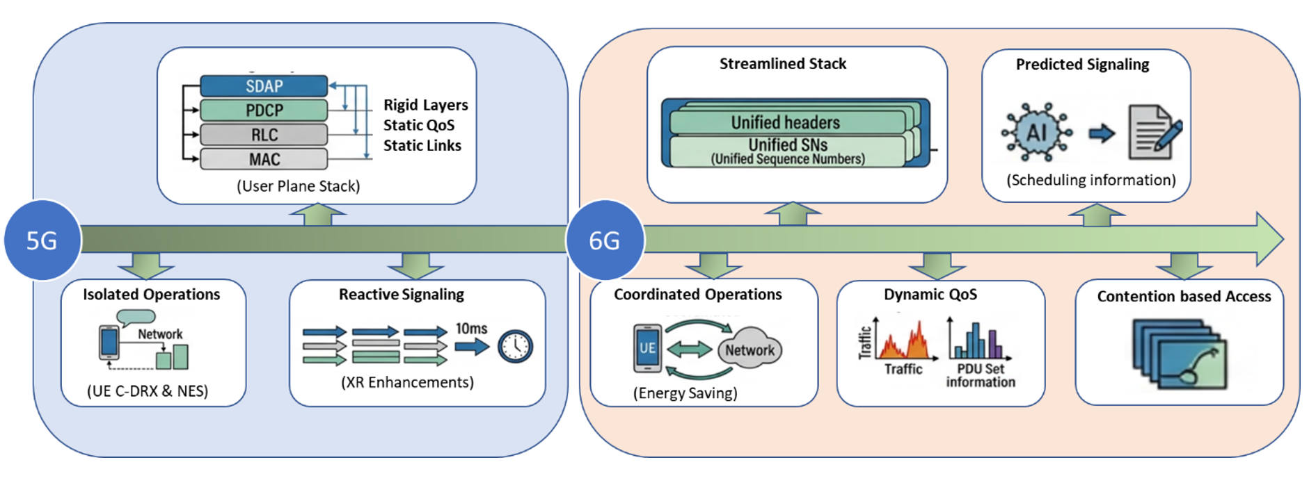
Figure 1. User Plane evolution
5G Lessons and Challenges
Technical Limitations
The 5G user plane faces throughput bottlenecks and latency spikes when processing dense, real-time traffic due to rigid frame structures and heavy header overhead. Its radio protocols struggle to dynamically adapt to ultra-reliable low-latency communication (URLLC) demands during sudden network congestion. Crucially, user plane operations and related signaling pathways operate on a reactive model, triggering remediation procedures only after performance degradation occurs rather than pre-emptively mitigating the issue.
Late Introduction of Key Features
One of the critical lessons learned from 5G's rollout was the timing of crucial functionalities. Many important features, for instance, network energy saving and extended reality, were introduced quite late in the standardization and deployment cycle. This meant that capabilities that could have significantly enhanced early 5G adoption or addressed critical needs were not available from day one.
Feature and Architecture Overload
5G standards introduced dozens of optional features, multiple split architectures, and alternative approaches. This extreme flexibility overwhelmed the user plane design, causing standardization overload, massive interoperability testing efforts and driving up software maintenance costs.
Fragmented Strategy
Spread across a multi-release roadmap, early 5G standardization often suffered from fragmented feature development rather than a unified design. A prime example is the disconnect between UE power-saving features introduced in early 5G releases and network energy-saving mechanisms developed for 5G-Advanced. Because these features were engineered in isolation, they lacked the unified design framework necessary to maximize end-to-end efficiency [2].
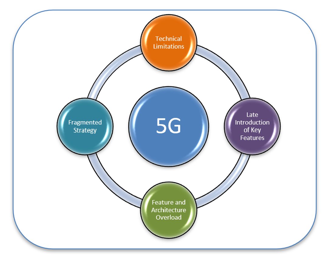
Figure 2. 5G lessons and challenges
New Directions for 6G User Plane
The 6G user plane is moving in clear directions to meet the ambitious scope, deployment and monetization goals for the 6G networks [1].
Diverse Services Addressed from the Start
Immersive and XR traffic, NTN, ISAC and diverse services all need to be considered in the design from the beginning rather than arriving as subsequent release add-ons.
Day-1 Deployment Demand
Building on the need for day-1 service support, the 6G user plane is prioritizing the immediate inclusion of crucial capabilities. Features like energy saving, XR handling, dynamic Quality of Service (QoS), secure Layer 2 (L2), and prediction framework are all slated for the very first release of 6G.
Streamlined Design
One option per user plane function is defined as the guiding principle. This lean approach aims to consolidate functionalities, curtail redundancy and have a hardware-friendly design, exemplified by concepts like fixed-size headers, single sequence number and integrated signaling.
Monetizable QoS
6G aims to provide guarantees that can be sold and verified per burst or per session, with exposed L2 KPIs, not just as a 5QI chosen at subscription time and frozen there.
Intelligence-Driven Approach
Prediction-based approaches are to be seriously considered in 6G with identity, validity and a defined lifecycle, rather than remaining an implementation detail hidden behind an existing information element (IE).
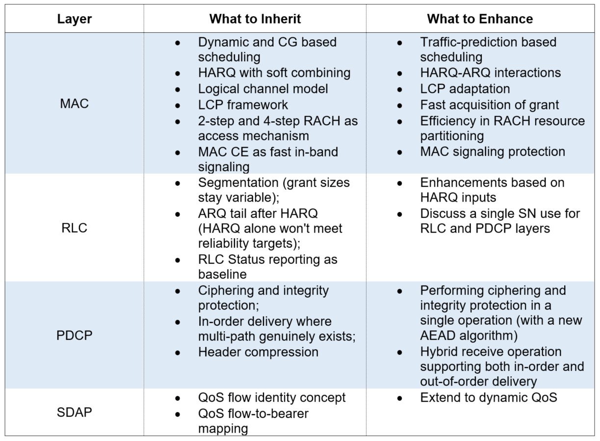
Table 1 outlines the explicit architectural inheritance principles and the proposed structural enhancements targeted for 6G protocol stack standardization.
Table 1. Directions for 6G inheritance and enhancements across user plane layers
Designing 6G User Plane
3GPP is presently progressing with designing 6G user plane and major discussion topics are as follows:
Lean protocol design – Keeping only essentials
One of the most active discussion points in 6G standardization revolves around the fundamental structure of Layer 2: Should 6G retain separate PDCP and RLC layers, much like 5G, or retain separate PDCP and RLC layers but have a single SN in pursuit of a leaner design?
A key aspect of this lean approach, heavily debated for PDCP and RLC, is Sequence Number (SN) Unification. Traditionally, protocol stacks like those in 5G maintain independent Sequence Numbers for different functions. For instance, PDCP uses SNs for ciphering, integrity protection, and in-order delivery, while RLC uses its own SNs for segmentation and Automatic Repeat Request (ARQ) retransmissions.
However, realizing this unified SN comes with its own set of complexities and overhead, which are central to the ongoing standardization discussion and decision:
Another aspect relates to optimizing user plane signaling for 6G. In 5G, Buffer Status Report (BSR) and Delay Status Report (DSR) signaling served similar overarching purposes: informing the network about the UE's buffer status and readiness to transmit. However, these were addressed as separate functionalities, adding to the complexity and potentially introducing redundancy. For 6G, the ambition is to achieve “the single-option, single-mechanism” principle and ensure an integrated signaling framework for similar tasks.
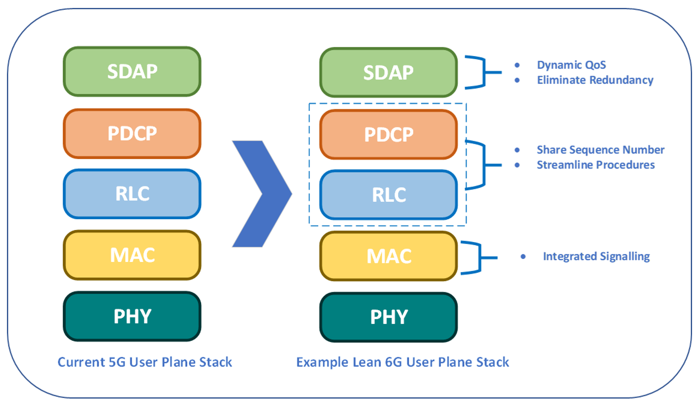
Figure 3. An example of lean protocol design for 6G user plane
Fast Scheduling - Reducing the Wait for “Grant”
In 5G architecture, the user plane operates on a request-grant mechanism. The sequence of events unfolds as follows:
This entire reactive chain, from the moment data arrives to the transmission of the first data byte, involves "two round trips" between the UE and the network.
To address the latency associated with waiting for a dedicated grant for BSR transmission, 6G is exploring "Fast UL Scheduling" mechanisms, including "Contention based approach”, either through a newly defined contention-based PUSCH mechanism, or by reusing the existing 2-step RACH procedure, which inherently includes a contention-based PUSCH transmission.
This approach aims to reduce BSR delivery latency by eliminating the need to wait for an initial UL grant, potentially addressing one of the "two round trips". Particularly for low traffic load situations, where collision probability may be more manageable, this approach could offer latency improvements compared to the legacy reactive approach, though collision handling at higher loads remains a key open issue.
Early Reporting – Predict and Act
In 5G NR, uplink resource allocation is fundamentally reactive. The UE only requests resources after data has already arrived in its L2 buffer. This triggers a multi-step handshake: a 1-bit Scheduling Request (SR) on PUCCH, followed by a Buffer Status Report (BSR) via a MAC Control Element (CE) on the scheduled PUSCH to report the volume per Logical Channel Group (LCG). For the delay-critical, bursty traffic expected in emerging 6G services, such as immersive XR and mobile AI, this reactive round-trip handshake introduces a latency penalty that can easily break strict QoS budgets.
Early reporting inverts this paradigm. It enables the UE to proactively report information about predicted upcoming data even before it reaches the L2 buffer, including two key metrics:
By leaving the actual prediction engine - whether AI-driven or statistical - to UE implementation, the standard can avoid algorithm lock-in while giving the scheduler the foresight to pre-allocate uplink grants. Furthermore, discussions within 3GPP also include how to control reporting overhead and misprediction behavior, and whether a performance monitoring mechanism in terms of the UE's traffic prediction is essential or not, for network to judge the usefulness of this feature and to determine whether/how to use it.
To quantify the impact of removing these reactive round trips, we performed a simulation, benchmarking the proposed early reporting framework against the legacy 5G baseline.
Looking at the access latency distribution under a medium load scenario (Figure 4), early reporting completely collapses the latency tail, allowing the vast majority of PDU sets to confidently beat their strict 10ms deadline. The result confirms that predictive L2 design is not just a theoretical optimization, but is beneficial for deploying scalable, high-capacity and immersive services in 6G.
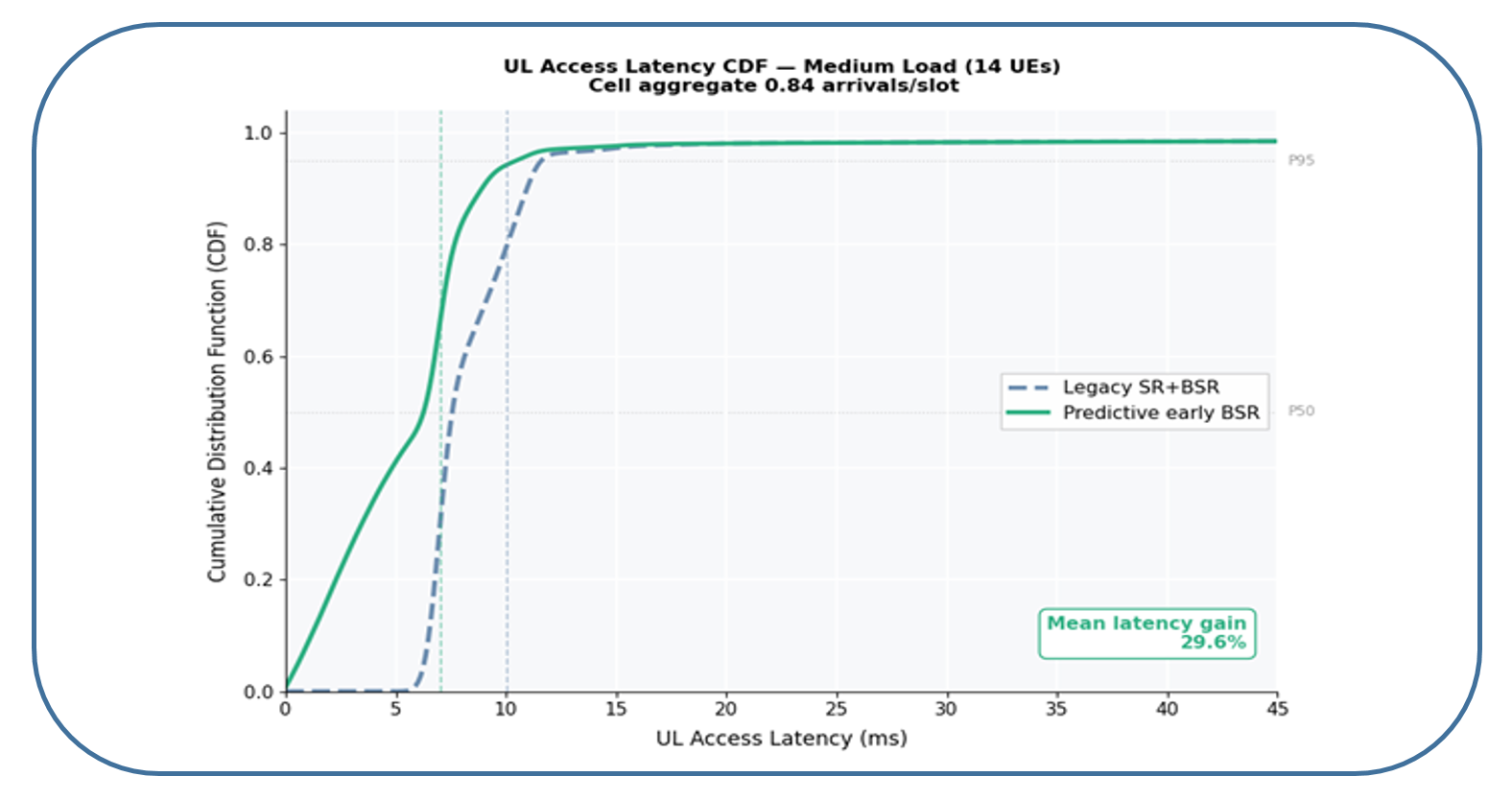
Figure 4. Comparison of 6G Early Reporting with 5G SR-BSR
Fast Retransmission – Cross-Layers Interactions
Delivering Extended Reality (XR) and immersive services over wireless networks presents a classic trade-off between strict bounded latency and ultra-high reliability. While Radio Link Control Acknowledgement Mode (RLC AM) is traditionally leveraged to ensure zero-loss operations via explicit Automatic Repeat Request (ARQ) retransmissions, its legacy design introduces an unacceptable latency penalty. Specifically, the RLC layer suffers from excessive delays due to its reliance on peer RLC status reports, which stem from the late detection of physical layer reception failures.
To enable faster ARQ retransmission in 6G, 3GPP discussions include cross-layer optimization via HARQ-ARQ interaction, allowing the transmitter to directly exploit the HARQ failure status (provided by the receiver), to trigger the ARQ retransmission(s) for the affected RLC Protocol Data Unit(s) (PDU(s)), instead of passively waiting for RLC status report to arrive later.
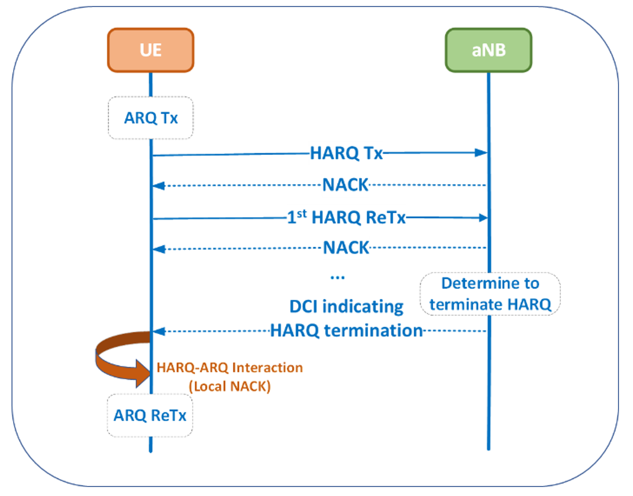
Figure 5. HARQ-ARQ interactions for fast retransmission
Dynamic QoS – Handling Variety and Variations
The 5G user plane uses QoS Flows to associate application traffic with defined latency, reliability and priority requirements. This approach works well when traffic characteristics remain relatively stable. Emerging 6G services such as mobile AI and immersive communication, however, can generate bursty and heterogeneous traffic whose requirements change over time. An application may switch its traffic between different QoS Flows, the QoS attributes of a flow may change, or individual PDUs or PDU Sets within the same flow may have different requirements. Applying uniform QoS treatment in such cases may lead to inefficient resource utilization or difficulty in meeting time-varying service requirements.
To address this, 3GPP is studying dynamic QoS, where QoS handling and L2 operation can adapt as service requirements change. This does not necessarily require replacing the existing QoS Flow framework. QoS Flow-level granularity, together with flexible 1:1 and N:1 mapping between QoS Flows and radio bearers, is being considered as a baseline, while finer differentiation can be supported through adaptive multi-QoS flow switching and multi-L2 parameter adaptation.
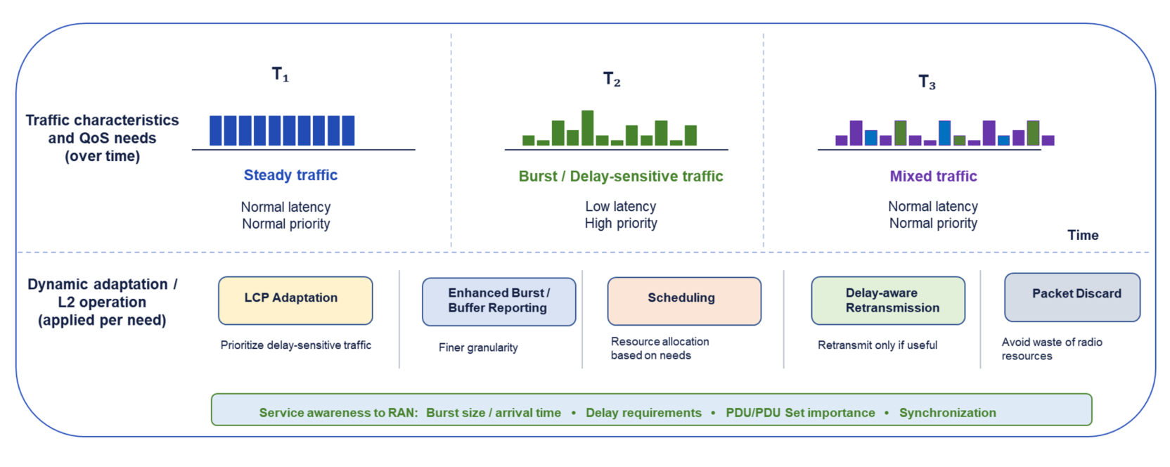
Figure 6. Dynamic QoS for varying service requirements
An important enabler for such adaptation is service awareness. Information such as burst size and arrival time, delay requirements, packet or PDU Set importance, and synchronization relationships between heterogeneous traffic can provide the RAN with better visibility of the traffic being carried. As illustrated in Figure 6, traffic characteristics and requirements may vary over time even within the same service. Making this information available to the RAN enables scheduling and resource allocation to better reflect the current service requirements.
Service-awareness information can also be used to enhance and dynamically adapt existing Layer-2 (L2) mechanisms. For example, LCP can take changing delay requirements into account when prioritizing uplink traffic, while enhanced BSR and burst information reporting can provide the scheduler with better visibility of bursty traffic. Similarly, retransmission and packet discard procedures can consider the remaining delay budget or importance of data to avoid spending radio resources on packets that are no longer useful. Such adaptations allow the 6G user plane to build on established L2 mechanisms while making their operation more responsive to the dynamically varying requirements of emerging services.
Energy saving – Coordinate and Conserve
In 5G, Connected-Mode Discontinuous Reception (C-DRX) was the cornerstone of device battery preservation. However, XR and ultra-reliable low-latency (URLLC) services demand highly dense channel monitoring. RAN2 is currently addressing this bottleneck by evolving the wake-up mechanism with C-DRX and/or DL-WUS:
On the network infrastructure side, the focus centers on turning off capacity cells, carriers, or secondary antenna arrays during low-load intervals. 3GPP is evaluating how this status change is conveyed to surrounding nodes and UEs, classifying methods into implicit and explicit mechanisms:
Another objective in 6G standards energy saving discussions is Joint Network-UE Coordination. In legacy architectures, network energy-saving (Cell DTX/DRX) and device energy-saving (UE DRX) operated in isolated silos, often causing misalignment where a network node would sleep just as a UE woke up to transmit. However, 6G aims to enable UEs to actively report their traffic patterns and preferred sleep configurations to the aNB.
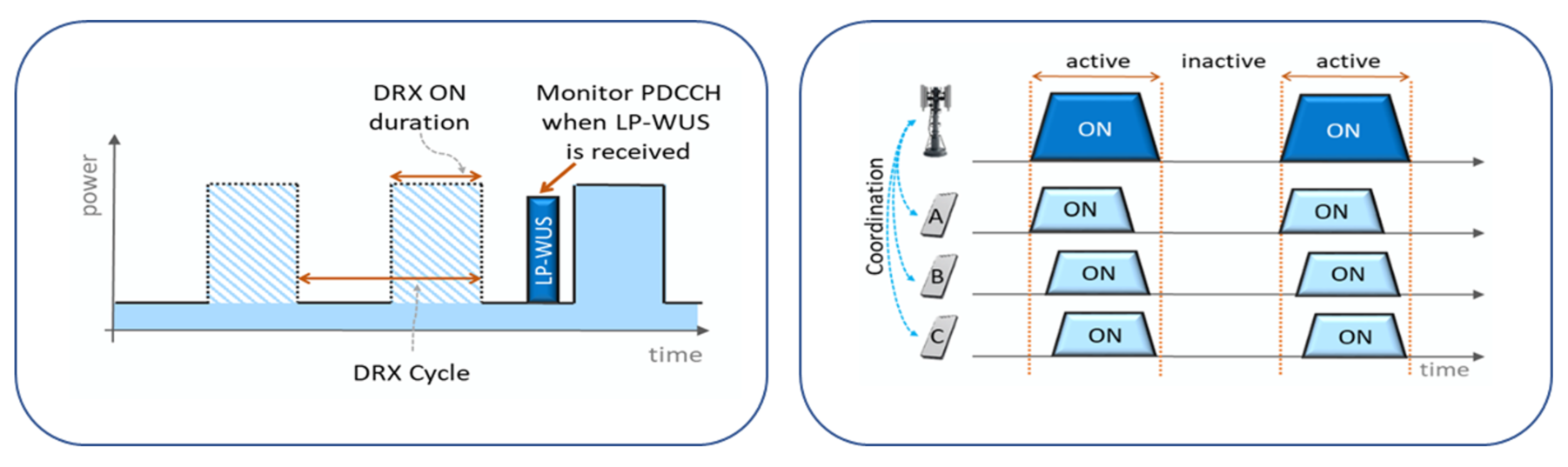
Figure 7. Energy saving for 6G – LPWUS with C-DRX (left) and Coordination between UE & Network (right)
AI and Intelligence-based Enhancements for User Plane
Beyond initial traffic forecasting, integrating AI directly into the 6G L2 protocol stack enables a highly adaptive, multi-use-case architecture. For Dynamic QoS, an embedded AI engine can continuously monitor transient traffic statistics and application-layer priority markers to dynamically adjust scheduling parameters—such as the Logical Channel Prioritization (LCP) token bucket size, transmission window limits, and maximum HARQ retransmissions. To ensure network control and prevent unexpected device behavior, this adaptation is strictly bounded within a network-configured operational range (e.g., minimum and maximum parameter envelopes provisioned via RRC).
For Coordinated Energy Saving, the AI engine can predict the "Time to Next Packet" to proactively adjust and optimize C-DRX parameters (such as extending the drx-InactivityTimer or switching from short to long sleep cycles), ensuring the primary RF transceiver is active right before predicted data bursts arrive and instantly powered down into deep sleep when an extended idle window is predicted.
Furthermore, this predictive intelligence can directly optimize the physical link layer through Early Reporting, where localized models forecast upcoming data bursts before they arrive in the buffer to proactively transmit expected arrival times and estimated volumes, allowing the scheduler to pre-allocate right-sized uplink grants and bypass the legacy request-grant handshake.
Together, these AI-driven use cases transform the user plane from a rigid, reactive pipeline into a highly efficient, self-optimizing protocol engine perfectly tailored to 6G's demanding traffic conditions. Whether such an intelligence framework is partially or fully standardized, or just guided for UE/Network implementations is subject to further discussion and decision in 3GPP.
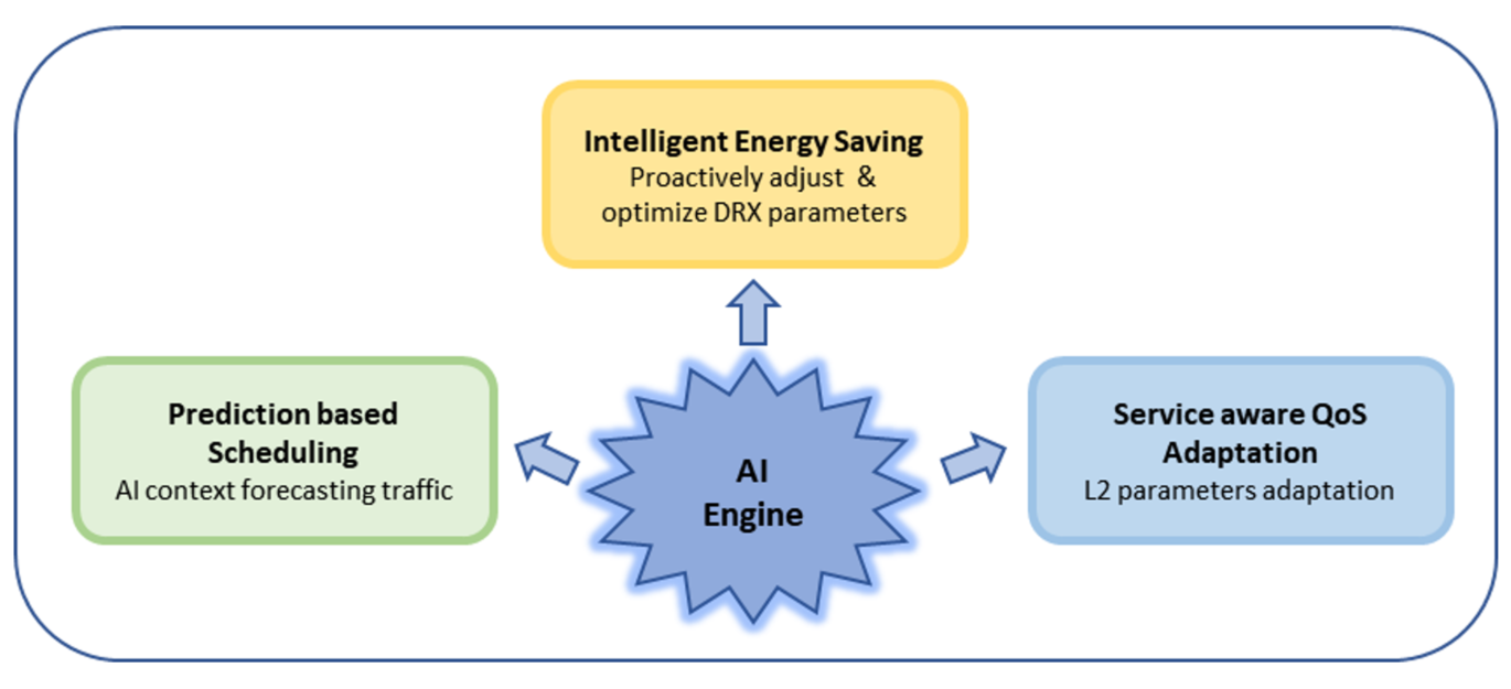
Figure 8. AI based enhancements for 6G user plane
Conclusion
This article has presented the design aspects for the evolution of the 6G user plane. This comprehensive evolution is transforming the user plane from a rigid, reactive pipeline into an adaptive, intelligent, and efficient protocol engine and is a fundamental prerequisite for deploying scalable, high-capacity, and immersive services in the 6G era. The ongoing 3GPP standardization efforts are crucial in realizing this next-generation user plane. Samsung is playing a pivotal role in realizing these future-oriented technical advancements and standardization steps across various 3GPP forums.
References
[1] 3GPP TR 38.914: "Study on 6G Scenarios and Requirements".
[2] Energy Saving for 6G Network: Samsung Research blog link