Communications
Physical-Layer Innovations Driving 6G Evolution
1. Introduction
Since the advent of mobile communication systems, each successive generation has marked a significant leap in technology, driving profound changes in how people connect, communicate, and access information. Among these advancements, core physical-layer (PHY) technologies—such as channel coding, modulation, and waveform—have continuously evolved, reaching near-Shannon capacity [1] in the current fifth-generation (5G) networks. Consequently, mere incremental improvements in link-level performance no longer represent meaningful value propositions for consumers, telecom operators, or equipment vendors.
Nonetheless, the question arises whether new PHY technologies remain essential as we move toward sixth generation (6G) networks. Our answer to this critical question is unequivocally “YES.” Considering the IMT-2030 requirements defined by ITU-R [2], 6G PHY technology developments must address four key strategic areas:
In this article, we will show our strategic directions for future advancements in channel coding, and modulation designs (waveform techniques were introduced in the previous blog posting [3]). Our aim is to outline how these foundational technologies should evolve, aligned explicitly with the demands and requirements anticipated in 6G. In this regards, Table 1 succinctly presents our slogan and proposal for each elementary technology. Ultimately, these advancements will provide tangible and impactful value to both service providers and end-users, fostering innovation and creating new business opportunities—effectively “Growing the Pie” for all stakeholders involved.

Table 1. Summary of proposed technologies
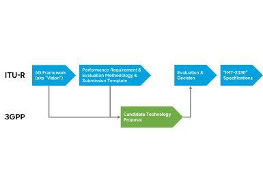
Fig. 1 illustrates the expected timeline for the standardization of physical-layer technologies in 6G. Key discussions on channel coding, modulation, and waveform are anticipated to take place in Release 20, the first official release of 6G. The overall direction and innovation level of these technologies will likely be shaped during the initial meetings, followed by more detailed technical decisions in subsequent sessions. While most physical-layer features are expected to be finalized within Release 20, certain aspects may be extended into later releases if necessary.

Figure 1. Expected timeline for 6G standardization and physical layer technologies
2. Channel Coding
Channel coding has been a cornerstone of reliable wireless communication, with major advancements achieved up to 5G through the adoption of low-density parity-check (LDPC) codes for data channels [4] and polar codes for control channels [5]. These technologies have pushed link performance close to the Shannon limit, making further incremental improvements appear marginal. However, as we move toward 6G, new physical-layer challenges emerge—enhancing energy efficiency, simplifying frameworks, and enabling AI-driven innovations—that demand a rethinking of channel coding strategies.
2.1 LDPC Codes
While LDPC codes have been instrumental in achieving near-optimal performance in 5G systems, their decoding process remains a significant source of complexity within the modem. As a result, LDPC decoding is typically implemented using dedicated hardware rather than software, standing as one of the few physical-layer functions resistant to full software-defined radio (SDR) integration for virtualized radio access network (vRAN). In the context of 6G, simplifying LDPC decoding to a level where it can be efficiently executed in software would bring substantial benefits—not only for modem design but also for improving operational flexibility and reducing upgrade costs.
To address this, we propose an additional energy-efficient base graph (EE-BG). Fig. 2 illustrates the overall concept of the LDPC coding system incorporating the proposed EE-BG. In the 5G system, two base graphs—BG1 and BG2—are used: BG1 for larger block sizes and higher code rates, and BG2 for smaller block sizes and lower code rates. These base graphs were designed solely to achieve excellent coding gains, often at the cost of increased decoding complexity. The complexity is largely determined by the number of non-zero elements in the base graph, and both BG1 and BG2 contain a relatively large number of such elements to maximize performance.
In contrast, the goal of the EE-BG is to significantly reduce the number of non-zero elements while maintaining acceptable performance. This makes it highly suitable for scenarios where decoding complexity, latency, or energy efficiency are of greater concern. User equipment (UE) and base stations (BS) can dynamically select among BG1, BG2, and EE-BG depending on specific requirements. For instance, when link-level performance is the priority, BG1 or BG2 may be chosen based on the code parameters. Conversely, when decoding efficiency is more critical, the EE-BG offers a practical alternative. The EE-BG shown in Fig. 2 is one example, and multiple EE-BG variants may be defined in the future to address more diverse requirements in 6G data transmission.

Figure 2. Proposed 6G LDPC coding system with EE-BG
Fig. 3 illustrates the number of processing blocks for the 5G BGs and the example EE-BG across various code rates. Since decoding complexity and power consumption are directly proportional to the number of non-zero elements (i.e., processing blocks), our EE-BG is expected to reduce decoding complexity and energy consumption by more than 50%. The performance loss is limited to up to 0.5 dB compared to 5G BGs, which is relatively minor given the substantial gains in complexity and energy efficiency. Moreover, this slight performance degradation can be compensated by enhancements in modulation techniques.

Figure 3. Number of processing blocks in the 5G BGs and the proposed EE-BG. The complexity is reduced by up to 70% compared to BG1 and up to 50% compared to BG2.
2.2 Polar Codes
In the 5G control channel, multiple channel coding schemes are defined based on the direction of transmission and the size of control information.
▪️ For UCI of 11 bits or fewer, Reed-Muller (RM) codes based on a single generator matrix are used.
▪️ For UCI between 12 and 19 bits, polar coding is employed, with parity-check (PC) coding and CRC used as outer codes. The PC code enhances error-correction performance, while the CRC supports error detection.
▪️ For UCI of 20 bits or more, only CRC coding is used as the outer code, complementing the primary polar code.
A key limitation of the 5G polar coding system is its restricted scalability. In the downlink, the maximum size of downlink control information (DCI) is limited to 140 bits due to constraints in the interleaver used for distributed CRC coding. In the uplink, the mother code length is fixed at 1024 bits, with a maximum of two concatenated code blocks. This means that for encoded payloads exceeding 2048 bits, portions of the polar codeword must be repeated. When the code rate is low—which is common in control channel applications—the total number of coded bits can exceed 2048, leading to excessive bit repetition and a significant loss in coding gain. As a result, the error-correction performance degrades severely when the UCI size exceeds approximately 500 bits, particularly under low-rate configurations.
To overcome these limitations, we propose a unified and scalable polarization-adjusted convolutional (PAC) coding scheme [6] for both downlink and uplink control channels in 6G. Originally introduced by Prof. Erdal Arıkan, the inventor of polar codes, PAC coding offers a novel paradigm that efficiently combines a polar code with a convolutional pre-transform. Unlike traditional concatenated schemes using parity-check (PC) or cyclic redundancy check (CRC) codes, the convolutional component in PAC coding enables the flexible and structured generation of parity bits tailored to the polar coding framework. These parity bits can be selectively utilized by the decoder for error correction or detection, depending on system requirements. This flexible structure is expected to overcome the scalability constraints of the 5G control channel and support robust, efficient signaling in future 6G networks. A comparison between the 5G control channel coding schemes and the proposed PAC-based approach is illustrated in Fig. 4.

Figure 4. Comparison of control channel coding schemes
The proposed structure of the polarization-adjusted convolutional (PAC) code can be described in more detail as follows. Unlike traditional concatenated polar codes, PAC codes embed a larger number of parity bits more densely across the control information bits. These parity bits can be flexibly utilized at the receiver depending on their position. For example, parity bits located in the earlier and middle stages of the successive cancellation decoding process are typically used for error correction, while those placed later in the sequence serve primarily for error detection. This mechanism is described in detail in [7]. As a result, PAC coding enables a unified decoding strategy without the need for separate outer codes such as parity-check (PC) or cyclic redundancy check (CRC) codes, as used in 5G polar coding. A single convolutional encoder can generate all necessary parity bits to support both error correction and detection as required. Moreover, unlike the distributed CRC approach in 5G downlinke, PAC coding does not require predefined interleavers that limit control information length, thereby allowing flexible and distributed parity placement.
Fig. 5 presents a performance comparison between the proposed PAC code and the 5G polar code, where the core polar structure is preserved and only the outer code is replaced with a convolutional transform. Both coding schemes are decoded using the successive cancellation list (SCL) decoder to ensure a fair comparison under equal complexity conditions. In the figure, the x-axis represents the length of the control information, while the y-axis indicates the required signal-to-noise ratio (SNR) in decibels (dB) to achieve a block error rate (BLER) of 0.1%. Each curve connects coding schemes with the same code rate. Since lower SNR values correspond to higher energy efficiency, curves that lie lower on the plot indicate better performance. As shown, the proposed PAC code achieves performance that is comparable to or slightly better than the 5G polar code under the same decoding complexity. At the same time, it offers greater flexibility, improved scalability, and unified applicability across both uplink and downlink control channels in 6G. To reiterate, our goal is to maintain near-optimal link performance while introducing the flexibility and scalability required for future 6G systems.

Figure 5. Comparison of 5G polar code and proposed PAC code performance under identical decoding complexity.
3. Modulation
In 5G systems, modulation techniques primarily relied on uniform constellations and simple rectangular interleaving-based bit-interleaved coded modulation (BICM). While effective in practice, this approach presents clear limitations from a theoretical perspective—particularly as communication demands intensify in 6G. As modulation orders increase to support higher data rates, the performance gap to the theoretical limit becomes more pronounced. Fig. 6 illustrates the deviation of each uniform modulation scheme from the BICM capacity, with the gap for 1024-QAM exceeding 1.5 dB. To close this gap, we propose enhancements that refine the interleaving strategy and optimize the constellation design, aiming to bring system performance closer to its fundamental limits.

Figure 6. Gap to capacity for uniform QAM schemes, highlighting 1.5~dB loss for 1024-QAM.
3.1 Bit-Interleaved Coded Modulation (BICM)
First, we introduce an advanced interleaving strategy tailored to the structure of LDPC codes. By applying a technique called density evolution (DE), we numerically analyze the relationship between demodulation and LDPC decoding across various modulation schemes [8]. Specifically, in high-order modulation, the bits transmitted within a single symbol experience different effective channels depending on their bit positions. Even when the symbol-level channel is modeled as a conventional Gaussian channel for system design, the resulting bit-level subchannels are inherently non-uniform and non-Gaussian. On the other hand, LDPC codes are also designed based on unequal error protection, where bits within a codeword get varying levels of decoding reliability. These bits are iteratively decoded in a highly interdependent manner. Therefore, to achieve optimal performance, the mapping of LDPC-coded bits to modulation symbols must carefully consider both the error protection structure of the LDPC code and the reliability characteristics of each bit-level subchannel induced by the modulation.
Following this principle, we design a BICM chain that carefully maps LDPC-coded bits to modulation symbols, as guided by the method proposed in [8]. Notably, the structure of LDPC codes originates from a compact base graph, which implies that certain groups of bits exhibit similar asymptotic performance. Specifically, within the parity-check matrix derived from the base graph, bits belonging to the same quasi-cyclic (QC) block are treated equivalently during the decoding process. This observation allows us to insert interleaving at the QC-block level, thereby enabling a more effective joint design between the LDPC code and the modulation symbols. In this context, the use of density evolution as a theoretical analysis tool plays a critical role: it reduces the design complexity to a practical level while guiding the construction of high-performance BICM mappings. Fig. 7 illustrates the block diagram of the proposed system with the insertion of QC-block-level interleaving.

Figure 7. Block diagram of the proposed system with QC-block interleaving between LDPC encoding and modulation.
Fig. 8 presents the performance of the BICM chain using a 64-ary uniform constellation, with and without the proposed QC-block interleaving designed through DE. Similar to Fig. 5, each curve connects the required SNR values to achieve a BLER of 0.1% for different control information lengths, while maintaining the same code rate. As shown, introducing QC-block interleaving yields a performance gain of approximately 0.5 dB. This gain is expected to increase further as the modulation order becomes higher, demonstrating the effectiveness of the proposed bit-to-symbol mapping strategy in high-order modulation scenarios.

Figure 8. BLER performance comparison with and without QC-block interleaving in 64-QAM BICM.
3.2 Constellation Shaping
In addition to interleaving optimization, we explore constellation shaping techniques to address the inherent inefficiencies of uniform constellations. By tailoring symbol distributions to better approximate theoretical capacity-achieving inputs, these methods significantly reduce the gap to Shannon capacity. As a result, they offer notable improvements in spectral efficiency and reliability, which are critical for meeting the demanding requirements of future 6G networks.
Among various shaping approaches, we focus on implementation-friendly one-dimensional (1D) geometric shaping. This technique has been widely adopted in several broadcasting standards such as DVB-T2 and ATSC 3.0 due to its practical simplicity and proven performance. Fig. 9 illustrates examples of 1D 1024-ary non-uniform constellations (NUCs) optimized for different code rates of LDPC codes, as used in ATSC 3.0 systems. As previously discussed in the interleaving subsection, the performance of BICM systems is determined by the interplay between the modulation and the underlying channel code. Therefore, these constellations are carefully designed to complement the specific characteristics of the associated LDPC codes, achieving improved shaping gains while maintaining implementation feasibility. Moreover, recent advances suggest that such constellations can be further optimized using AI/ML techniques, enabling data-driven design that jointly considers channel behavior, decoder structure, and system-level performance trade-offs [9].

Figure 9. 1D 1024-ary non-uniform constellations (NUCs) designed for different LDPC code rates in ATSC 3.0 systems.
The proposed 1D-NUC structure retains compatibility with existing demodulation architectures used for uniform constellations, allowing it to be implemented with minimal additional complexity. By designing the constellation such that the in-phase (I) and quadrature (Q) components are identical and separable, demodulation can be performed independently on each axis, significantly reducing computational demands. For instance, while two-dimensional NUCs for 1024-ary modulation require distance calculations between a received symbol and all 1024 constellation points, a 1D-NUC only requires comparisons against 32 constellation amplitudes per axis. This not only simplifies the computation but also opens the door to efficient approximations such as piecewise linear mapping, enabling high-order modulation with minimal decoder overhead.
Fig. 10 presents the block error rate (BLER) performance of a 256-ary modulation scheme under three different constellation designs: uniform quadrature amplitude modulation (QAM), one-dimensional non-uniform constellation (1D-NUC), and two-dimensional non-uniform constellation (2D-NUC). All configurations share the same bit-interleaved coded modulation (BICM) chain with a 5G LDPC code of rate 1/3. Both the 1D-NUC and 2D-NUC were designed using AI/ML-based optimization techniques as described in [9]. As illustrated, 1D-NUC significantly outperforms uniform QAM while maintaining low implementation complexity. Notably, to achieve a BLER of 1%, 1D-NUC requires approximately 0.5 dB less signal-to-noise ratio, demonstrating a substantial gain. This improvement goes beyond mere link-level enhancement, offering meaningful contributions to the overall energy and cost efficiency of the communication system.

Figure 10. BLER performance comparison of 256-ary modulation using uniform QAM, 1D-NUC, and 2D-NUC with a 5G LDPC code (rate 1/3).
4. Conclusion
To realize the full promise of sixth-generation (6G) wireless networks, fundamental innovations in physical-layer technologies are no longer optional—they are essential. In this work, we proposed a cohesive set of forward-looking advancements in channel coding, modulation, and waveform design, each tailored to address emerging challenges in energy efficiency, scalability, and uplink coverage. These innovations are not only technically sound but also practically impactful, paving the way for more flexible, sustainable, and cost-effective system architectures. Our vision sets the foundation for building smarter, greener, and more resilient communication infrastructures that will extend the boundaries of connectivity and create transformative value for industry and society alike. With bold yet feasible innovation, we aim to grow the pie for all stakeholders in the 6G era.
Link to the paper
[1] https://ieeexplore.ieee.org/document/9691350
References
[1] C. Shannon, “A mathematical theory of communication,” The Bell System Technical Journal, vol. 27, no. 3, pp. 379–423, 1948.
[2] ITU-R, “Framework and overall objectives of the future development of IMT for 2030 and beyond,” Recommendation ITU-R M.2160-0, Nov. 2023. [Online]. Available: https://www.itu.int/rec/R-RECM. 2160-0-202311-I/en
[3] N. Ferdinand, Bongsung Seo, Joonyoung Cho, and Yosub Park, Waveform enhancement for energy efficiency in 6G. [Online] Available: https://research.samsung.com/blog/Waveform-enhancements-for-energy-efficiency-in-6G
[4] R. Gallager, “Low-density parity-check codes,” IRE Trans. Inf. Theory, vol. 8, no. 1, pp. 21–28, 1962.
[5] Erdal Arıkan. “Channel polarization: a method for constructing capacity-achieving codes for symmetric binary-input memoryless channels,” IEEE Trans. Inf. Theory, vol. 55, no. 7, pp. 3051–3073, Jul. 2009.
[6] Erdal Arıkan, From sequential decoding to channel polarization and back again. 2019. [Online]. Available: arXiv:1908.09594
[7] M. Jang, J. Lee, S.-H. Kim, and K. Yang, “Improving the tradeoff between error correction and detection of concatenated polar codes,” IEEE Trans. Commun., July, 2021.
[8] M. Jang, H. Jeong, S. Myung, K.-J. Kim, J. Park, and S.-H. Kim, “Analysis and design of QC-LDPC coded BICM ensembles based on RCA density evolution,” IEEE Trans. Commun., Apr. 2022
[9] P. Madadi, J. Cho, C. J. Zhang and D. Burghal, "AI/ML Optimized High-Order Modulations," in Proc. IEEE International Conference on Communications (ICC), Rome, Italy, 2023, pp. 6373-6378