Communications
IEEE 802.11bn (Ultra-Hig Reliability (UHR), Wi-Fi 8)
1. Introduction
Historically, IEEE 802.11 (commonly known as Wi-Fi) standards have prioritized boosting maximum theoretical performance with each iteration—evolving from 2 Mbps (Legacy IEEE 802.11) to 36 Gbps (IEEE 802.11be, Wi-Fi 7)—by implementing advancements such as extended bandwidth, higher-order modulation, and increased spatial streams. However, the upcoming IEEE 802.11bn (Wi-Fi 8, and also called as ultra-high reliability (UHR)) standard shifts its focus beyond peak performance in ideal conditions. It aims to deliver reliable and stable performance in challenging environments, such as coverage edges, while also prioritizing latency-sensitive traffic through innovative technologies. Under these objectives, the Project Authorization Request (PAR) document for IEEE 802.11bn outlines the following key goals:
- At least 25% higher throughput in challenging signal conditions
- 25% lower latency at the 95th percentile of the latency distribution
To further enhance service stability, the following additional goals have been established
- 25% fewer dropped packets especially when roaming between access points
- Reduce power consumption
- Improved Peer-to-Peer (P2P) operation
The standardization work for IEEE 802.11bn began in November 2023, and as of July 2025, IEEE 802.11bn has finalized draft version 1.0, which defines the technical scope of this standard. Efforts to refine its technical maturity are ongoing, with the standard slated for publication in March 2028. The Wi-Fi Alliance (WFA) is an organization that manages certifications for applying IEEE 802.11 standard technologies to markets. WFA plans to finalize the certification test plan in June 2027 and launch the certification in December 2027. After the certification is launched, it is expected that Wi-Fi 8 (IEEE 802.11bn) compatible products that have received this certification will be released in the market.
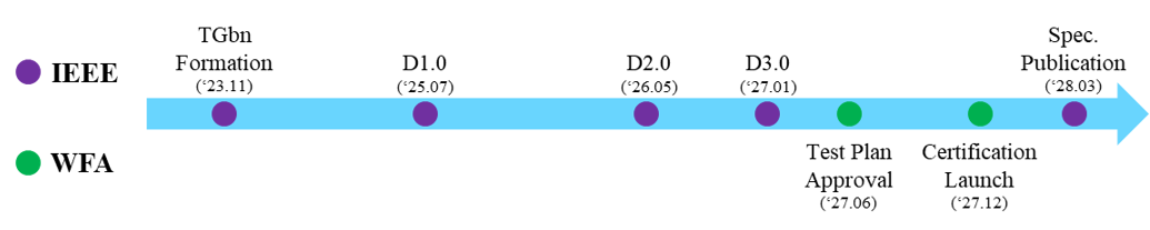
Figure 1. IEEE 802.11bn Milestone
In this article, we explore the technologies currently being introduced to achieve these objectives and their practical implications for users. We believe that maintaining consistent performance—rather than merely offering high performance—will significantly enhance user experience, aligning with the vision of IEEE 802.11bn standardization efforts.
2. Higher Throughput and Reliable Connection
(PAR Scope: At least 25% higher throughput in challenging signal conditions)
Traditional IEEE 802.11 technologies have aimed at achieving performance gains under optimal wireless channel conditions. However, there is still a gap in ensuring a more uniform user experience, especially in challenging signal environments. To compensate, users often had to deploy additional access points (APs) to achieve the desired performance levels. With the introduction of IEEE 802.11bn, two key technologies have been implemented to enhance coverage and ensure robust real-world performance. As the number of out-of-service areas decreases and practical performance increases in poor wireless environments, the need for extra AP installations at home is eliminated.
- Enhanced Long Range (ELR)
As the demand for IoT devices and smart home systems continues to rise, the necessity for extended long-range has become increasingly important. Such scenarios demand reliable connectivity over longer distances, particularly in difficult propagation conditions characterized by obstacles, multipath effects, and interference. The ELR format is introduced in IEEE 802.11bn to improve link-margin for distant/edge stations (STAs). It’s targeted especially at scenarios with constrained STA transmit power or harsh propagation—thus offering greater reach albeit at lower data rate.
Two technologies have been applied to secure a wider transmission range. One is the repetition at the resource unit (RU) unit level, and the other is the addition of a separate preamble for ELR, enabling frame detection even at low SNR. The ELR physical layer (PHY) protocol data unit (PPDU) demonstrates how these technologies have been implemented.
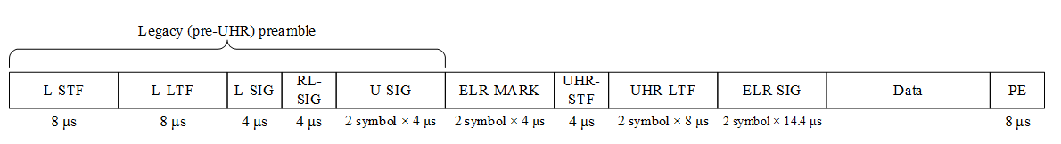
Figure2. UHR ELR PPDU Format
Legacy preamble to ensure compatibility and detection by legacy devices. ELR-MARK symbols (two symbols) to indicate the ELR mode. When UHR-STF and UHR-LTF are used for ELR, a 3 dB power boosting has been applied to enable better signal detection. ELR data portion is encoded at robust modulation and coding schemes (MCS), possibly with repetition, to allow lower signal-to-noise ratio (SNR). Bandwidth for ELR PPDU is fixed to 20 MHz only and only 1 spatial stream is supported. Modulation is limited to BPSK (MCS0) and QPSK (MCS1), resulting in PHY data rates of 1.67 Mbps and 3.33 Mbps. ELR PPDU uses repeated 52-tone “regular RU (RRU)” blocks in a 20 MHz band (i.e., four repeats of a 52-tone RU) to increase frequency-diversity or repetition gain. This quadruplication technique delivers a precise 6 dB improvement.
- Distributed Resource Units (DRUs)
In prior IEEE 802.11 generations, uplink transmissions (from a STA to an AP) often suffer poorer link budget compared to downlink. Increasing transmit power could mitigate this issue; however, regulatory constraints restrict devices from exceeding the power spectral density (PSD) limit defined for narrow bandwidths. For example, in 6GHz, for a non-AP STA which is associated with an AP in low power indoor bands, the PSD limit is -1dBm/MHz in US. To address this, the concept involves distributing the tones of small RUs across a wide bandwidth (refer to below figure). This approach allows devices to enhance their total transmit power while complying without exceeding regulatory PSD requirements. Accordingly, even in the same channel conditions as previous generation STAs, higher throughput performance can be achieved.
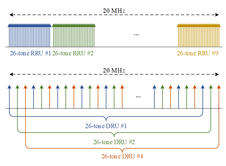
Figure 3. Example of RRU and DRU tone spacing
Above figure demonstrates the tone allocation schemes for RRUs and DRUs. While a RRU (which consisted with 26-tone) occupies a continuous subset of subcarriers, each DRU disperses its tones across the entire distribution bandwidth. By using DRUs, it can deliver up to an 11 dB power gain when small RUs are spread over a 40 or 80 MHz channel. Consequently, leveraging DRUs enables multiple devices to simultaneously improve their overall transmit PSD and spectral efficiency by utilizing different DRUs in uplink OFDMA.
3. Enabling Low Latency and Improving System Capacity
(PAR Scope: 25% lower latency at the 95th percentile of the latency distribution)
In today's hyper-connected world, diverse use cases are rapidly emerging which include immersive experiences with extended reality (XR) headsets, AI-driven applications, multi-user gaming, and high-quality video streaming to name a few. Such innovations demand a stable, reliable, and low-latency wireless connection. In turn, this emerging trend is also resulting in increasing deployment of IEEE 802.11 enabled devices and APs creating denser wireless environments. Such dense wireless environments pose significant challenges in providing a suitable, reliable and low latency wireless system.
IEEE 802.11bn is addressing these technical challenges by supporting on the one hand, low latency traffic with various enhancements like low latency indication (LLI) & prioritized-enhanced distributed channel access (P-EDCA), while on the other hand, addressing challenges of dense wireless deployments by developing opportunities to better utilize the system’s capacity thereby improving the overall latency. Features such as non-primary channel access (NPCA) and dynamic sub-band operation (DSO) aid in better utilizing system capacity which in turn helps improve the overall system latency.
3.1 Enhancements to Improving Latency
Modern IEEE 802.11 networks carry a mix of traffic types. A large file download can tolerate a few extra milliseconds or even seconds of delay, but a video call or augmented reality (AR)/ virtual reality (VR) stream cannot. Traditional IEEE 802.11 already includes access categories (voice, video, best effort, background) to give time-sensitive packets better treatment, yet under heavy load, even high-priority traffic can occasionally sit in a queue longer than desired, stretching the “tail” of the delay distribution and causing glitches or freezes. IEEE 802.11bn addresses this with a combination of smarter prioritization on the channel access (P-EDCA) and a way for devices to explicitly say “there is urgent data waiting” (LLI).
- Prioritized EDCA (P-EDCA)
P-EDCA builds on the existing enhanced distributed channel access (EDCA) mechanism that IEEE 802.11 uses for contention-based channel access. In simple terms, EDCA controls how long each traffic category waits and how aggressively it contends for the channel. IEEE 802.11bn refines this so that high-priority flows see fewer long delays, specifically targeting a reduction in the ‘tail’ of access delay for those packets.
The standard also includes rules to keep this from becoming unfair. P-EDCA-capable STAs advertise that capability in the UHR medium access control (MAC) capabilities, and APs enable or tune P-EDCA parameters using dedicated operation elements and update procedures. This allows compatible devices to benefit from sharper prioritization while limiting the impact on legacy devices that still use traditional EDCA.
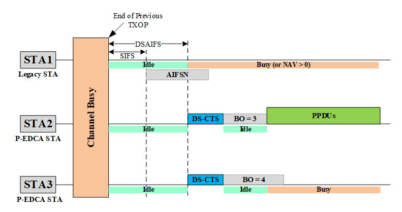
Figure 4. Example of P-EDCA operation
The Figure above depicts an example P-EDCA operation. STA1 is a legacy STA, whereas STA2 and STA3 are P-EDCA STAs. After a previous TXOP ends, all three STAs intend to get access of the channel. However, unlike the legacy device, which needs to wait longer (arbitration interframe space (AIFS) duration) before it can start contention, the P-EDCA STAs (STA2 and STA3) can send a clear to send (CTS) frame, called defer signal CTS (DS-CTS), to reserve the medium for their contention. Between the two P-EDCA STAs, subsequently, STA2 wins the P-EDCA contention and starts transmitting the P-EDCA PPDUs.
The result is not necessarily higher average throughput, but a tighter distribution of delay for urgent packets—fewer “spikes” where a voice or game-input frame waits much longer than usual.
- Low-latency Indication (LLI)
While P-EDCA makes the fast lane itself better, LLI is about signaling when a device actually has urgent data buffered and waiting. In IEEE 802.11bn, LLI allows a device that is currently a “transmission opportunity (TXOP, an interval of time during which a particular AP or STA has the right to initiate frame exchange sequences onto the wireless medium) responder” (a STA that is being served within a transmission opportunity granted to another STA or AP) to indicate that it has pending low-latency traffic.
STAs that support LLI advertise this through dedicated LLI capability fields in the UHR MAC capabilities element. A STA with the option activated becomes an “LLI STA” and can report two types of urgency: buffered low-latency traffic destined to the AP itself, and buffered urgent traffic for P2P destinations.
The key mechanism is a feedback message: the LLI STA embeds a low-latency indication bit inside a response frame sent back to the TXOP holder. This bit signals whether urgent packets are waiting for uplink or P2P delivery, associated with previously established low-latency service streams.
The AP (or other TXOP holder) is then expected to factor this indication into its scheduling decisions within the current or upcoming TXOPs, for example, by quickly granting uplink slots to trigger uplink transmission for the requesting STA or allocating a TXOP so that the requesting STA can use the granted airtime for transmitting urgent traffic to another P2P device. By requesting scheduling from the AP in this manner, traffic indicated with low latency requirements can be processed more quickly. This enables more flexible handling of real-time traffic, such as voice or gaming applications.
3.2 Enhancements to System Capacity
Recent developments in IEEE 802.11 technology have enabled the use of wider bandwidths for handling user traffic. Nonetheless, baseline aspects of IEEE 802.11 hinder the utilization of full potential of these wide bandwidths, limiting the efficient use of system capacity in current designs. IEEE 802.11bn aims to enhance the system capacity with features like NPCA and DSO which ultimately impacts the overall gain in throughput and reduction in system latency.
- Non-Primary Channel Access (NPCA)
In all the previous IEEE 802.11 specifications, there has been a heavy dependence on the primary 20 MHz channel. This channel is used for all essential MAC layer signaling including Beacon transmissions, Probe Request/Responses, Trigger frames, Channel announcements and so on. As a result, more often than not, the primary 20 MHz channel is seen to be busy possibly even originating from a neighboring or overlapping basic service set (OBSS). Traditional channel access hence becomes restricting in such scenarios where the entire operating channel bandwidth (e.g., 80 MHz/160 MHz/320 MHz) is blocked even though alternative 20 MHz channels are not occupied. IEEE 802.11bn solves this problem by defining the NPCA feature that enables the device to use a different 20 MHz channel as the primary channel temporarily (a.k.a. NPCA primary channel). The IEEE 802.11bn specification defines detailed rules, associated parameters and conditions to utilize the NPCA feature. The AP indicates various parameters including the NPCA primary channel, parameters required to determine condition(s) when NPCA primary channel switch is allowed and some associated delays in performing the switch. The STA also indicates it’s own switching delays when NPCA feature is enabled. The IEEE 802.11bn specification further outlines the aspects that aid in switching to the NPCA primary channel when the primary 20 MHz channel is busy, transmitting on the NPCA primary channel including the associated channel access rules and switching back to the BSS primary channel. NPCA hence plays a critical role in leveraging the wider bandwidths offered by IEEE 802.11be and IEEE 802.11bn, turning underutilized channels into valuable transmission opportunities when the primary 20 MHz channel is busy due to OBSS transmissions, thereby also improving the overall throughput and latency of the system.
- Dynamic Sub-band Operation(DSO)
Today’s deployments are quite diverse. Some STAs usually operate at lower bandwidths (e.g., 20 MHz, 80 MHz) and others at higher bandwidths (e.g., 160 MHz), while the APs can operate at much higher bandwidths (e.g., 320 MHz). In such a scenario, a large part of the AP bandwidth gets under-utilized due to absence of STAs supporting higher bandwidths. At the same time, the lower bandwidths are overcrowded to support multiple devices with overlapping bandwidths. However traditionally there was no mechanism that allowed the AP to switch operating bandwidths of STAs considering devices with multiple bandwidths. In the absence of such a mechanism, when diverse mixed supported bandwidth capable devices are in the BSS, the whole system’s performance can be underutilized. So, to let an AP utilize cleaner spectrum and schedule users more efficiently, IEEE 802.11bn has defined DSO which is an AP-controlled mode where an AP can tell selected STAs to hop to a specified sub-band (a.k.a. DSO sub-band), within the AP's operating bandwidth but outside the STA's operating bandwidth, and perform frame exchanges there (e.g., hop to an 80 MHz chunk inside a 320 MHz BSS). The specification provides a mechanism for STA and AP to harmonize on the preferred DSO sub-band where the switch can occur. This can also be seen as an enhancement to the overall latency of the system as the devices are distributed across AP’s operating bandwidth and there is lesser interference and delays which enhances overall system performance. In the figure below, an illustration is shown that indicates the DSO switch for a STA from it’s current operating bandwidth to a new operating bandwidth within AP’s 320 MHz operating bandwidth using a sequence of initial control frame (ICF) and initial control response (ICR) frames to perform the switch. In previous IEEE 802.11 generations, the sub-band where the STA operates for it’s current operating bandwidth could not be changed allowing only serial transmissions within the current sub-band. However, with the introduction of DSO, the sub-band of operations can be dynamically switched which enables parallel and simultaneous transmissions across all the sub-bands where the AP operates. This improvement enhances channel utilization, resulting in reduced latency and increased overall network throughput.
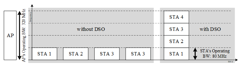
Figure 5. Overview of DSO Operation
4. Reliable Connection in Mobility
(PAR Scope: 25% fewer dropped packets especially when roaming between access points)
Over the years, IEEE 802.11 has introduced numerous technologies aimed at reducing the time required for basic service set (BSS) transition (a.k.a. roaming), which refer to the movement of STAs between APs. However, these efforts have primarily focused on minimizing the duration of disconnections. In IEEE 802.11bn, the goal is to implement technologies that provide seamless services from the user's perspective (which is called as seamless mobility domain (SMD) BSS transition). IEEE 802.11bn introduces SMD with the multi-link operation (MLO, which was introduced in IEEE 802.11be, Wi-Fi 7) to enable ultra-reliable, low-latency BSS transition. SMD is logical entity which is a collective set of multiple APs that collaboratively manages STA’s transitions. When a STA connects to an AP within the SMD, its association and authentication are managed by the SMD management entity (SMD-ME), rather than just a single AP. STA's associated and authenticated state is preserved throughout the SMD BSS transition, and contexts (MAC protocol states, quality of service (QoS) parameters, and security information) between the current AP and STA are transferred to the target AP. Based on this, the SMD BSS transition facilitates seamless movement of the STA from its current AP to a target AP within the same SMD, and this is possible because the SMD-ME assists in maintaining connectivity at higher layers (e.g., IP level connectivity). In addition, by using MLO, this enables make-before-break transitions, where a new link is established before the old one is released, preventing service interruption
The SMD BSS transition outlines how a client moves between APs within the same domain. It follows three coordinated phases:
1. Prepare: The current AP transfers the STA's contexts to the target AP through the SMD-ME before the movement begins. A new link is also established between the STA and the target AP, but it remains deactivated in power save mode.
2. Execute: The client activates the new link to the target AP without performing a full re-authentication, ensuring continuous connectivity.
3. Complete: The old AP releases its temporary state once the new connection is stable.
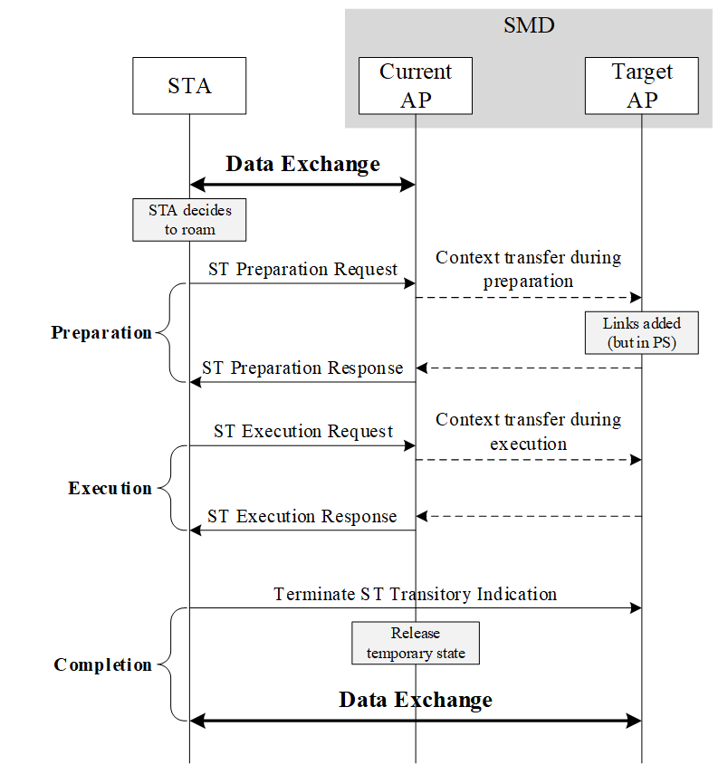
Figure 6. Example of SMD BSS Transition Procedure
By implementing this procedure, the STA maintains a continuous connection within the SMD, ensuring that the reliability and latency of data exchange remain unaffected during roaming.
5. Reduce power consumption
Recent advancements in IEEE 802.11 technology have pushed performance limits typically, with an added cost that includes having more radios with multi-link operations, wider bandwidths, complex PHY layer operations, more control signaling and so on. At the same time, networks are filled with battery powered devices, wearables, smart home devices, even smartphones that are dependent on the limited battery source for power and cannot afford to be power inefficient. Further in alignment with sustainability goals, technological advancements need to be energy efficient and hence reducing the overall energy consumption is very important. In order to support these requirements, IEEE 802.11bn defines several new power save features to support STAs and APs (especially mobile-APs). Among these, dynamic power savemic power save (DPS) is a feature supported in both STAs and mobile-AP that allows the devices to save power by listening to the radio with lesser capabilities and wake up with full capabilities only on need basis. The specification also defines other power save features that optimize power save signaling across multi links called multi-link power management (MLPM).
- Dynamic Power Save (DPS)
With the introduction of multi-link radios, support for a higher number of spatial streams, more MCS and wider bandwidths to improve throughput, across various generations of IEEE 802.11, the power consumption has also drastically increased. Existing power saving schemes are found to be more static, suitable for single radio devices, with fixed intervals of sleep and wake up. However, with a plethora of devices and their varied requirements, a more dynamic and flexible power save scheme was necessary that allows the STAs and mobile-APs to determine their own configurations for operating in low power and high power states. DPS introduces exactly this aspect. A DPS STA (a non-AP STA or a mobile-AP) can configure itself to operate in low capability mode for power save and upon the reception of an initial control frame (ICF) from the peer STA can transition to a high capability mode and handle the data reception. The low capability parameters are determined by the DPS STA and indicated to it’s peer in operating mode and parameter update procedures, while the high capability parameters are the current operating parameters of the device. The parameters include bandwidth, MCS, number of spatial streams (NSS) and PPDU formats. DPS feature enables the devices to save power while still supporting packet reception according to the low capability mode of operation. Further the specification goes a step ahead in allowing the STAs to configure flexible parameters in the low capability mode. This is especially useful for the wide range of devices (e.g., wearables, smartphones, smart home appliances, XR headsets and so on) present in a typical IEEE 802.11 ecosystem and each device now has flexibility to choose its own low capability parameters thereby trading off power save and performance based on requirements and use cases. Another challenge the IEEE 802.11bn group is working to address in outlining the DPS specification is the management of DPS operation for a mobile-AP and its impact on legacy devices.
With the introduction of DPS operation for a mobile-AP, the battery powered APs can still provide a stable connection to the clients in areas where infrastructure APs are not available. It is hence an important requirement to save power in a mobile-AP through the enablement of DPS feature. In the figure below, there is an illustration of two STAs using DPS feature differently. While STA1 has flexibly configured the low capability mode and is able to exchange data even in low capability mode, STA2 has configured minimum default parameters in low capability and transitions to high capability upon reception of ICF for data exchange.
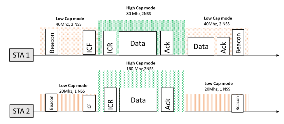
Figure 7. Example of DPS Operation
6. Improved Peer-to-Peer (P2P) operation
IEEE 802.11 is usually thought of as STAs talking through an AP: phone → router → TV. In practice, many modern experiences depend on devices talking directly to each other instead: phone casting to a TV, camera sending footage to a laptop, tablets collaborating in a classroom, XR headsets streaming to a PC. This is P2P communication.
Earlier generations of IEEE 802.11 supported P2P, but often in a “best effort” way. Performance could collapse as soon as the network became busy or the environment became crowded with neighboring networks. IEEE 802.11bn makes P2P a core design target and introduces two dedicated mechanisms:
• TXSPG – TXOP Sharing with a P2P Group (for P2P on the main IEEE 802.11 channel)
• Co-CR – Coordinated Channel Recommendation (for P2P on separate, cleaner channels)
Together, these features aim to make device-to-device network more predictable, even in dense and noisy environments.
6.1 TXSPG: Reserved Airtime for P2P Groups
On a typical home or office network, P2P traffic on the main channel (i.e., AP’s channel) competes with everything else: video meetings, file downloads, smart home chatter, background updates. Even if two devices are close together, packets still contend with all other devices associated with the same AP. Latency can spike at exactly the wrong moment. TXSPG changes this by allowing the IEEE 802.11bn AP to allocate reserved airtime slices to a group of devices that need to talk to each other. In IEEE 802.11 terms, it lets the AP “share” part of its TXOP with a P2P group. Within that time slice, only members of the group are allowed to transmit, so their traffic is protected from unrelated background load. One STA in the group effectively acts as a leader, describing the group’s needs to the AP. The AP then schedules recurring time windows for that group, based on overall capacity. When each window starts, the AP signals that this group now has priority. Inside the slice, STAs can exchange data intensely and with much lower risk of random delays caused by other clients. A gaming setup provides a concrete example: a console talking to several phones and tablets for local co-op play while other members of the household stream video or sync data. With TXSPG, the console’s P2P group can receive a recurring reserved window. Controller inputs, state updates, and audio frames flow during that window with far more stable latency, so the group experience feels responsive even when the rest of the network is busy.
6.2 Co-CR: Coordinated Channel Choices for P2P
Not all P2P traffic needs to stay on the main IEEE 802.11 channel. Moving a P2P link to a separate channel can greatly reduce contention, but choosing the right channel in a dense apartment building or office is difficult. Many independent networks overlap, each with its own view of which channels are “free.” Co-CR addresses this by enabling APs to coordinate their suggestions. APs exchange information—using the multi-AP coordination framework, introduced in IEEE 802.11bn—and agree on which channels, and in some cases which time periods, will be kept relatively quiet for P2P. Once a common plan is established, each AP advertises consistent P2P channel guidance using management frames. In a dense residential building, this can create something like a “P2P zone” in the spectrum: a specific channel where most IEEE 802.11bn APs intentionally reduce regular traffic. Devices forming a P2P link—such as a laptop casting 8K video to a TV—can move that link onto the coordinated channel and enjoy a much more stable experience than if they chose independently.
The combination of TXSPG and Co-CR represents a shift in how IEEE 802.11 treats P2P. Instead of being an afterthought, P2P traffic gains tools for predictability:
• Groups, not just individual devices, can be given scheduled airtime on the main channel.
• Neighboring APs can align on channel choices so P2P links do not suffer from conflicting policies.
This matches the broader IEEE 802.11bn goal of improving not only peak speeds but also latency consistency and robustness for interactive applications. XR workloads, multi-screen collaboration, and real-time creative pipelines stand to benefit directly.
7. Conclusion
At the current stage, with the completion of draft version 1.0, numerous comments have been submitted to enhance the quality of the specification. Standardization meetings are actively ongoing to address these feedback points. The specification is expected to be finalized by March 2028, and around that time, a variety of devices capable of utilizing IEEE 802.11bn are anticipated to enter the market.
Samsung Research is actively participating in the standardization process, proposing additional technologies that can deliver enhanced experiences for users of our devices, ensuring these advancements are reflected in the specification.